
Speaker

a technology of speakers and amplifiers, applied in the field of speakers, can solve the problems of affecting the sound quality of the speaker, the possibility of large harmonic distortion, and the power linearity of the speaker, and achieve the effect of reducing distortion and increasing audio outpu

Inactive Publication Date: 2009-05-12
PANASONIC CORP
View PDF12 Cites 5 Cited by
  • Summary
  • Abstract
  • Description
  • Claims
  • Application Information

AI Technical Summary

Benefits of technology

"The present invention is a speaker with a concave frame, a diaphragm, a voice coil, a magnetic circuit, and a suspension holder. The speaker has symmetrical edges and the inner periphery of the suspension holder and the diaphragm are fixed to the voice coil outside of the magnetic gap. The magnetic circuit has a magnet outside of the frame and the magnetic gap is pushed into the frame. This design reduces distortion and increases audio output."

Problems solved by technology

However, according to a recent trend toward higher performance of speakers, the existence of damper 8 is causing serious problems.
That is, due to a large degree of non-linearity of mechanical load and asymmetry between the behavior of voice coil 4 moving toward magnetic circuit 1 and the behavior of the voice coil moving toward a direction opposite to magnetic circuit 1, there is a possibility of generating large harmonic distortion and, at the same time, worsening power linearity.
Accordingly, in so far as a suspension is to be structured by combining damper 8 and edge 6, it is difficult to reduce harmonic distortions by solving the problems of non-linearity and asymmetry, and enhancement of speaker performance is not satisfactory.
However, there are problems to be solved with the speaker shown in FIG. 8.

Method used


Image

  • Speaker
  • Speaker
  • Speaker

Examples


Embodiment Construction

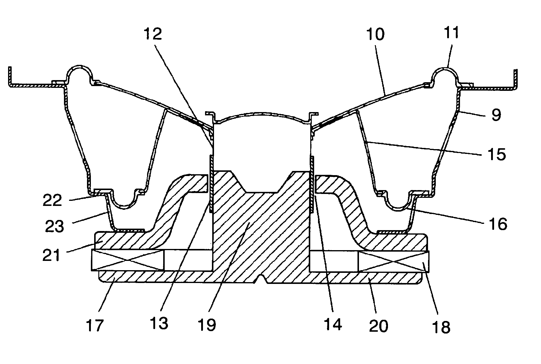
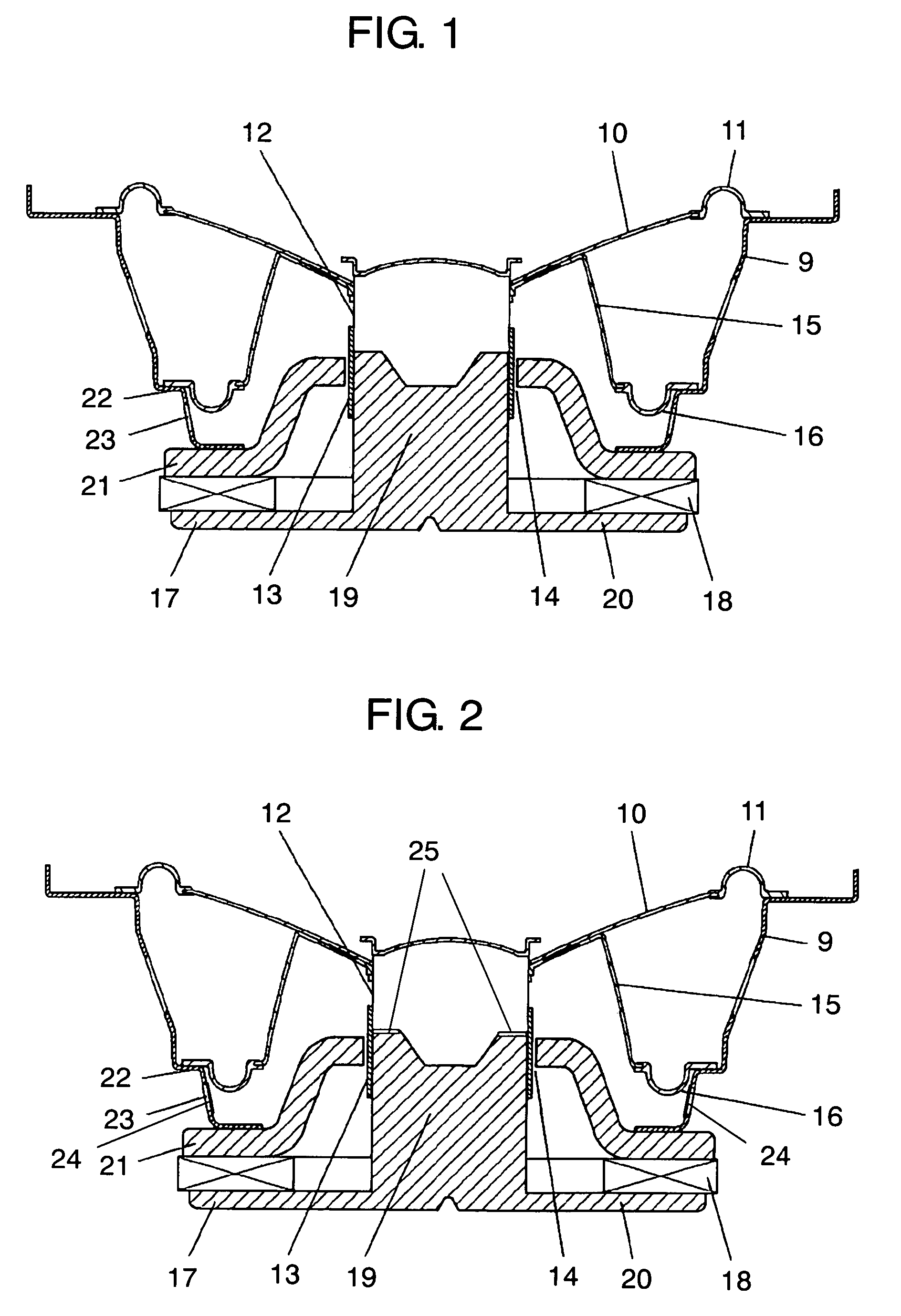
[0023]The speaker of the present invention has the following structure. The speaker includes a concave frame having an opening on the upper side, a diaphragm provided in the opening of the frame with its outer periphery fixed to the edge of the opening of the frame through a first edge, a voice coil provided on the bottom side of the diaphragm, a magnetic circuit into a magnetic gap of which at least a part of the voice coil is movably disposed, and a suspension holder having an outer periphery of being is fixed to the frame through a second edge on the bottom side of the diaphragm within the frame. The first and the second edges are substantially symmetrical with respect to a space in between. The magnetic circuit has a magnet provided outside of the bottom of the frame with its outer periphery extending to at least beyond the center of the second edge. The magnetic gap of the magnetic circuit passes through the bottom of the frame and reaches inside of the frame.

[0024]In this way,...


PUM


Abstract

A speaker including a frame, a diaphragm fixed to the frame through a first edge, a voice coil, a magnetic circuit, and a suspension holder fixed to the frame through a second edge is disclosed. The first and the second edges are spaced apart, and substantially symmetrical in shape with respect to the space between them. The inner periphery of the suspension holder and the inner periphery of the diaphragm are fixed to a part of the voice coil which is located outside of the magnetic gap of the magnetic circuit. The magnetic circuit has a magnet provided outside of the bottom of the frame. The outer periphery of the magnetic extends at least beyond the center of the second edge. The magnetic gap of the magnetic circuit is disposed inside of the frame, above a bottom surface of the frame.

Description

[0001]This application is a U.S. National Phase application of PCT International Application PCT / JP2005 / 014069.BACKGROUND OF THE INVENTION[0002]1. Field of the Invention[0003]The present invention relates to speakers for use in various acoustic systems.[0004]2. Description of the Related Art[0005]A description of the structure of a conventional speaker will be given referring to FIG. 5. This speaker has magnetic circuit 1; a voice coil 4, of which at least coil section 3 is movably provided inside magnetic gap 2 of magnetic circuit 1; a diaphragm 5, the inner periphery of which being coupled to an external part of magnetic gap 2 of magnetic circuit 1; and a frame 7 to which the outer periphery of diaphragm 5 is coupled through edge 6. By inputting an electric signal fed from an audio amplifier and the like to coil section 3 of voice coil 4, voice coil 4 is excited, the force of excitation is transmitted to diaphragm 5, and diaphragm 5 converts the electric signal into a sound by vib...

Claims


Application Information

Patent Timeline
Patent Type & Authority Patents(United States)
IPC IPC(8): H04R1/02H04R11/02H04R9/06
CPCH04R9/025H04R7/24H04R9/041H04R9/06
Inventor FUNAHASHI, OSAMU
Owner PANASONIC CORP
Learn More