Side-mounted position indicator for flapper check valve

a position indicator and flapper technology, applied in the direction of functional valve types, instruments, liquid/fluent solid measurement, etc., can solve the problems of inability to adjust the indicator, the indicator is not expensive and complicated, and the use of the upper clean-out port is impeded, so as to prevent leakage or pressure loss

Inactive Publication Date: 2009-05-19
GA INDS
View PDF15 Cites 35 Cited by
  • Summary
  • Abstract
  • Description
  • Claims
  • Application Information

AI Technical Summary

Benefits of technology

[0006]The present invention provides a simple check valve position indicator that is mounted on the side of a valve. This design allows for an upper clean-out port as well as an adjustable position indicator. The position indicator of the present invention threads into an existing pipe tap located at the top of a valve assembly. The invention preferably includes a bushing which houses a round roller with O-ring seals to prevent leakage or pressure loss from within the valve. A channel bracket including a threaded clean-out port is attached to the bushing. A tripper rod is attached to the bottom of the roller and is positioned within the valve body to touch the valve flapper. A visual position flag or other indicator device or assembly is attached to the side of the roller. For example, an electrical switch may also be added to the exterior indicator assembly for transmitting an “open” or “closed” signal back to a control device. In one embodiment, a mechanical spring is attached to the visual flag and channel bracket. This spring holds the tripper rod and plastic ball firmly against the valve body flapper. When no flow is present in the valve, the spring tension aids in positioning the valve flapper in a closed position, and the position flag or other indicator visually shows this “closed” position on the channel bracket. When flow develops in the valve, the flapper lifts upward toward the valve cover. This lift also raises the tripper rod and causes the roller to rotate. The position flag or other indicator attached to the side of the roller, in turn, moves to visually show an “open” position for the valve on the channel bracket.

Problems solved by technology

Users of check valves desire to verify the position of the valve (open or closed), because lack of flow could indicate a serious condition in the pipeline.
Prior position indicators of these types are expensive and complicated, however.
First, because the indicator assembly uses a rod that protrudes from the top of the valve, this design precludes the use of an upper clean-out port.
Finally, the indicator is not adjustable.

Method used


Image

  • Side-mounted position indicator for flapper check valve
  • Side-mounted position indicator for flapper check valve
  • Side-mounted position indicator for flapper check valve

Examples


Embodiment Construction

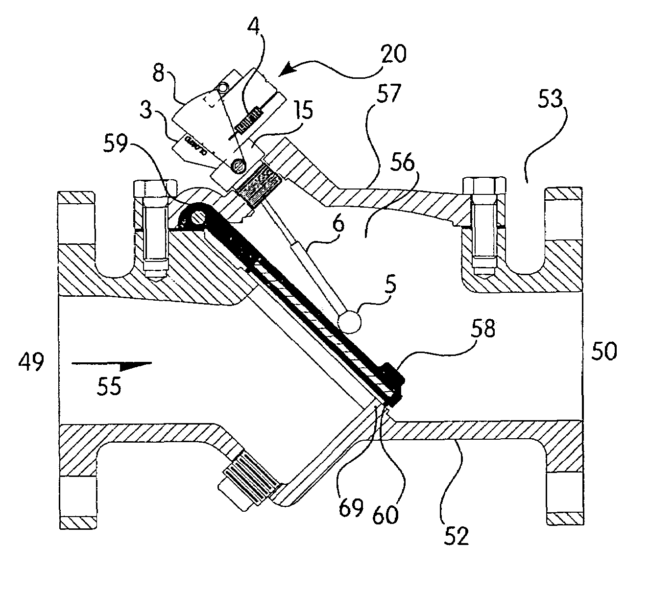
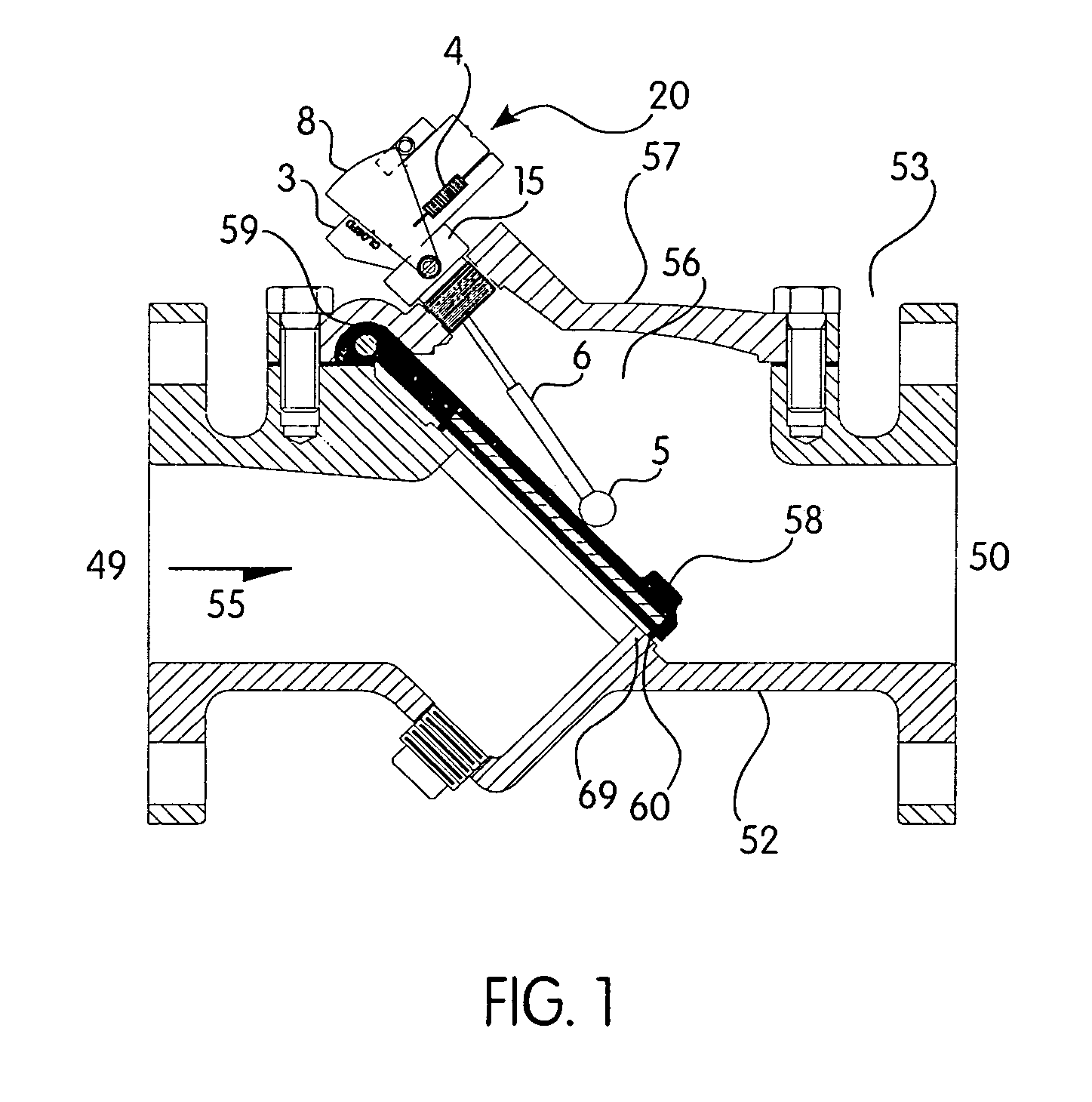
[0014]Referring to FIGS. 1 and 2, the position indicator (20) of the present invention is designed for use with a flapper swing check valve assembly (53) with a valve body (52) that includes an inlet (49) and outlet (50). The media flow path is indicated by a flow arrow (55). The valve body (52) has a top opening (56) which is enclosed by a cover (57). The valve body (52) also houses a flapper (58). This flapper (58) includes a hinged attachment (59) to the valve body (52), which allows the flapper (58) to rotate between open and closed positions within the valve body (52). The flapper (58) is normally in the closed position, as shown in FIG. 1, when no media flow is present in the valve body (52). This flapper (58), when in the closed position, rests against a metal seating area (69). The flapper (58) can incorporate a sealing bead (60), or other sealing mechanism, that insures drop tight sealing under pressure.

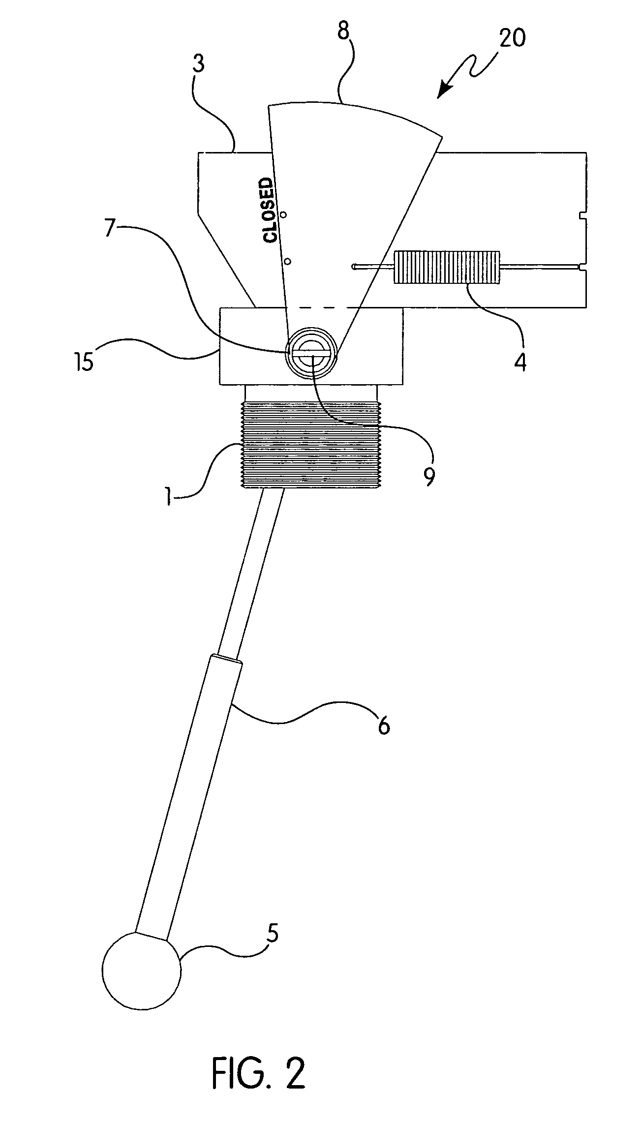
[0015]Referring more specifically to FIGS. 1, 2 and 3, the preferred em...


PUM


Abstract

The present invention is a side-mounted position indicator for use with a flapper check valve. The indicator is located outside the valve body and attaches to an internal, cylindrically-shaped roller that allows limited rotation about one axis. This roller has a tripper rod that extends from one side of the roller and has a round, non-marring plastic ball on its opposite end. The ball is held in contact with the valve flapper using a mechanical spring. A separate flush port is provided to allow for periodic internal cleaning without substantial disassembly.

Description

FIELD OF THE INVENTION[0001]The present invention pertains to a side-mounted position indicator for a flapper check valve.BACKGROUND OF THE INVENTION[0002]It is commonly known to use a check valve with a closure mechanism consisting of a disc that pivots within the valve body. Check valves are designed to stop flow reversals within a piping system. The disc closure mechanism typically pivots about a hinge that is fully contained in the valve body. Such check valves are disclosed in U.S. Pat. No. 4,054,153 and U.S. Pat. No. 5,341,840.[0003]It has also been commonly known to use an indicator mechanism to show the check valve disc position. Users of check valves desire to verify the position of the valve (open or closed), because lack of flow could indicate a serious condition in the pipeline. Thus, it has been known to attach an indicator mechanism to the pivot point of the disc such that the disc position, i.e. open or closed, can be observed by an external indicator dial. U.S. Pat. ...

Claims


Application Information

Patent Timeline
Patent Type & Authority Patents(United States)
IPC IPC(8): F16K37/00F16K15/00G01F1/28
CPCF16K15/031F16K37/0008Y10T137/7898Y10T137/8225Y10T137/8292
Inventor COLTON, JR., G. A. PETESCHWEITZER, RICHARD R.
Owner GA INDS
Why Eureka
Try Eureka