Processing method and apparatus

a processing method and a technology of curved shapes, applied in the direction of optical surface grinding machines, manufacturing tools, lapping machines, etc., can solve the problems of damage to the polishing surface of the polished surface, and achieve the effect of high precision positioning, not hindering the processing to the work, and high precision positioning

Active Publication Date: 2009-05-19
FUJITSU LTD
View PDF27 Cites 5 Cited by
  • Summary
  • Abstract
  • Description
  • Claims
  • Application Information

AI Technical Summary

Benefits of technology

[0008]Accordingly, with the foregoing in mind, it is an exemplary object of the present invention to provide a processing method and apparatus that can form a complicate shape on a work with high precision.
[0009]In order to achieve the above object, a processing method according to one aspect of the present invention includes the steps of elastically deforming a jig together with a work, the jig having been mounted on a work, compressing the work against a polishing surface, and moving the work and the polishing surface relative to each other. Instead of relying only upon local changes of the pressure used to compress the work against the polishing surface, this processing method elastically deforms the jig together with the work by applying the load to predetermined positions on the jig. Instead of directly providing application points on the work, a large jig having application points may maintain a desired number of application points for a small work. In addition, a thin work is prevented from getting damaged since the work receives no direct compression force. Moreover, particularly when the application points are provided to the jig instead of directly providing the work with application points, an application of the tensile load becomes easy without damaging the work. The jig elastically deforms with the work instead of controlling the work's contact pressure only by plural point loads, and maintains the uniformity of the contact pressure distribution.
[0010]The elastically deforming step may include the step of controlling a load applied to the jig at a predetermined position for an elastic deformation, by assuming that there is a linear relationship between the load and a deformation amount of the work associated with the load and / or by approximating with an arc a deformation amount of the work associated with the load. These approximations can simplify the control, and lessen the burden of the control software. The load controlling step includes, for example, the steps of calculating a necessary polishing amount distribution based on a difference between a current shape of the work and a target shape of the work, calculating positional information of the work and a relative speed distribution between the work and the polishing surface, and calculating the load based on the polishing amount distribution and the relative speed distribution.

Problems solved by technology

In particular, if a large load is applied to the jig suddenly, deforms the jig, and the work contacts the polishing surface, a polished surface would damage the polishing surface when the polished surface is a curved surface.

Method used


Image

  • Processing method and apparatus
  • Processing method and apparatus
  • Processing method and apparatus

Examples


Embodiment Construction

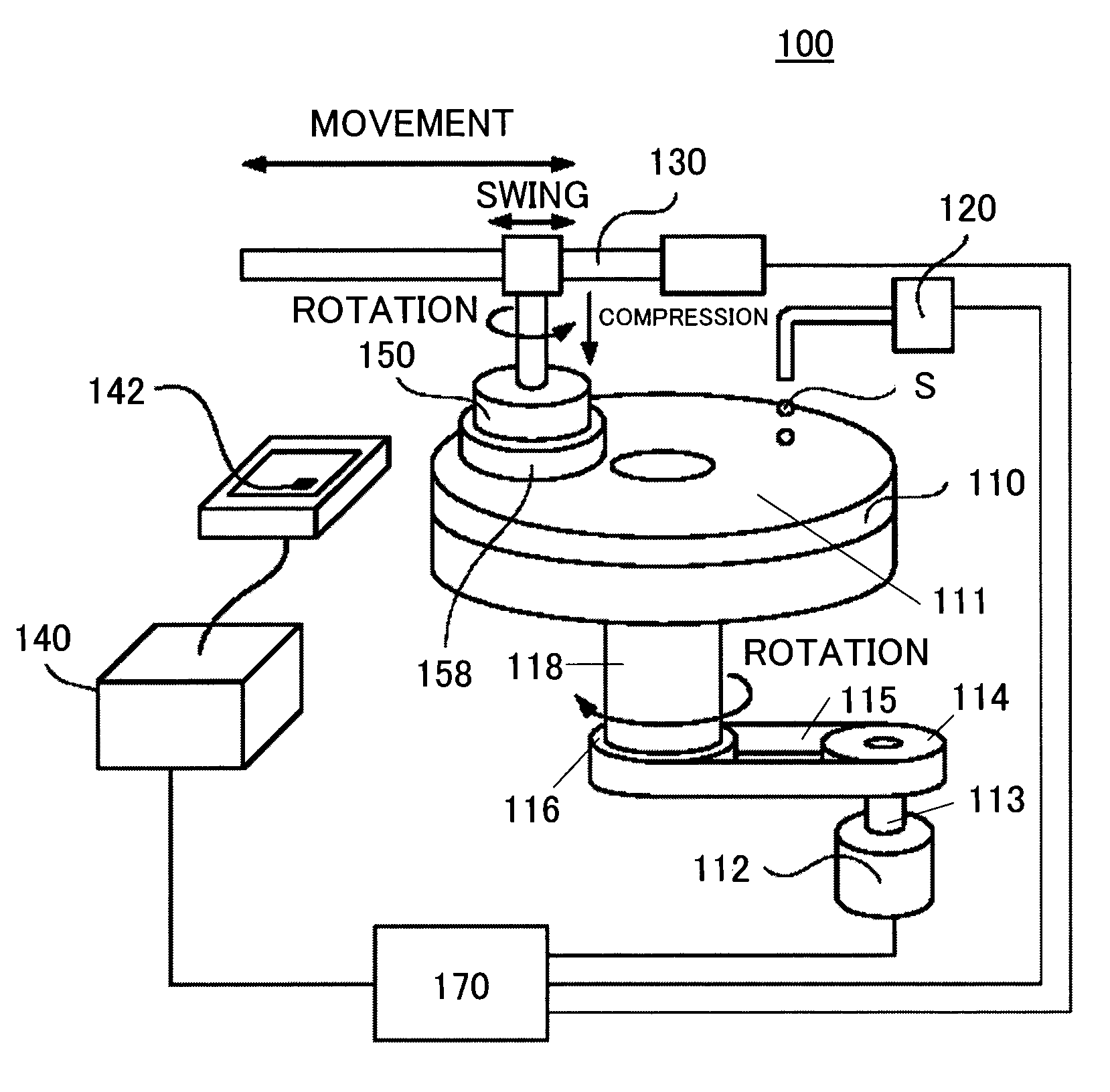
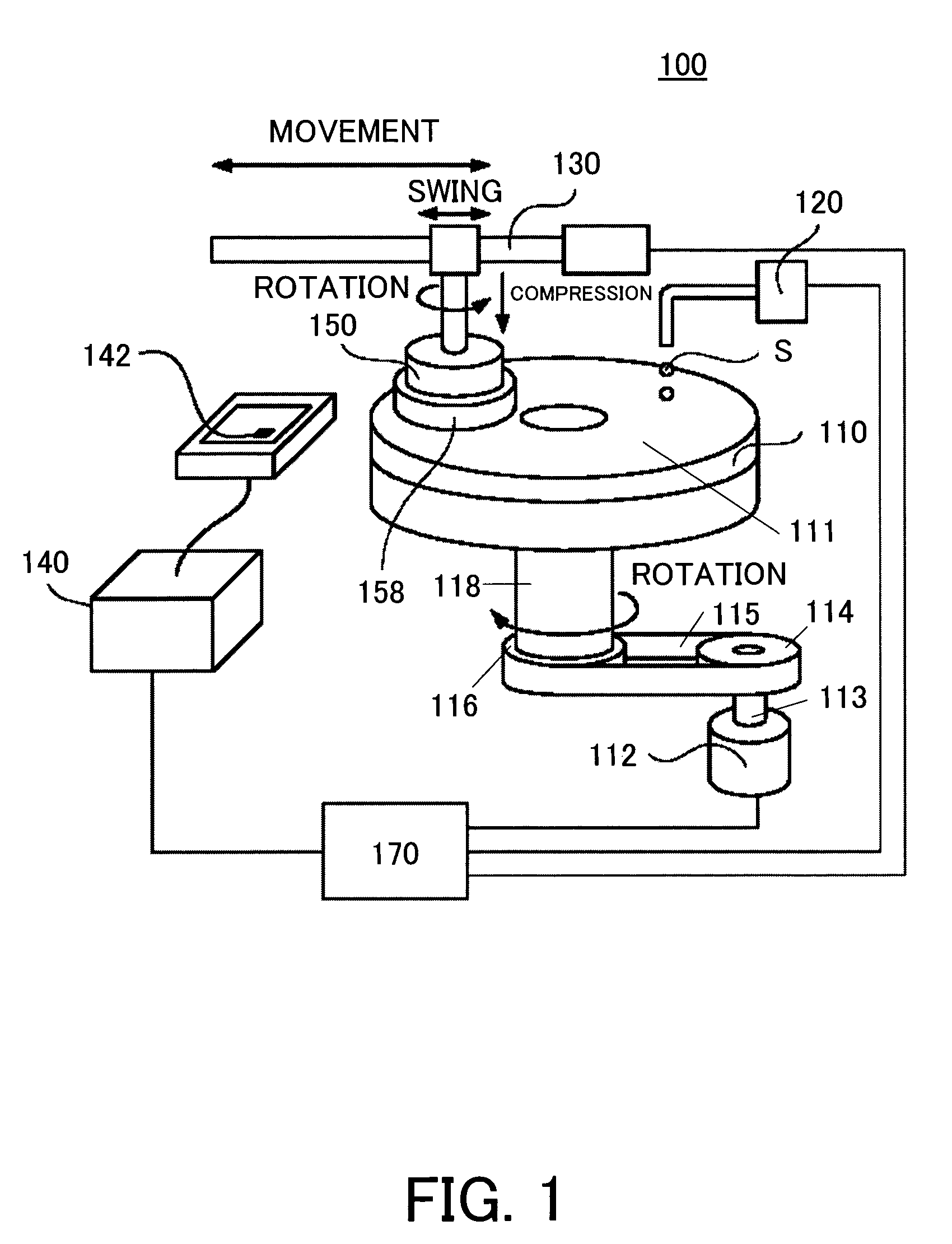
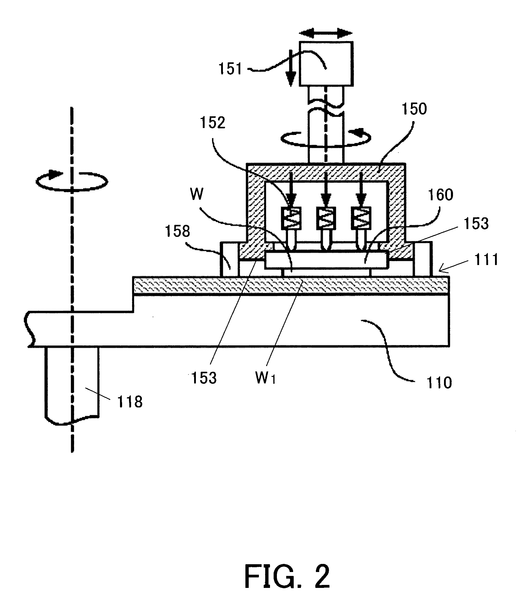
[0049]A description will now be given of a processing apparatus 100 according to one embodiment of the present invention, with reference to FIGS. 1 and 2. Here, FIG. 1 is a schematic perspective view of the processing apparatus 100. FIG. 2 is a schematic sectional view of a processing head 150 used for the processing apparatus 100.

[0050]The processing apparatus 100 provides lapping, which is polishing that introduces abrasive grains called slurry S between a work W supported by a processing head 150 and a polishing tool called a lapping machine 110, and moves the work W relative to the lapping machine 110 while the work's polished surface W1 contacts the lapping machine's polishing surface 111, so that the slurry S between them polishes the polished surface.

[0051]The processing apparatus 100 includes five modules, as shown in FIG. 1, i.e., a lapping machine 110, a slurry supply pump 120, a processing arm 130, a shape measuring unit 140, and a processing head 150. Each module is conn...


PUM

PropertyMeasurementUnit
thicknessaaaaaaaaaa
thicknessaaaaaaaaaa
areaaaaaaaaaaa

Abstract

A processing method includes the steps of elastically deforming a jig together with a work, the jig having been mounted on a work, compressing the work against a polishing surface, and moving the work and the polishing surface relative to each other.

Description

[0001]This application is a continuing application, filed under 35 U.S.C. §111(a), of International Application PCT / JP03 / 07970, filed Jun. 23, 2003, it being further noted that priority is based upon International Application PCT / JP03 / 04083, filed Mar. 31, 2003, which is hereby incorporated by reference herein in its entirety as if fully set forth herein.BACKGROUND OF THE INVENTION[0002]The present invention relates generally to a three-dimension curved shape forming method and apparatus, and more particularly to a polishing method and apparatus. The present invention is suitable, for example, for a curved shape formation and surface processing for an optical element that are required to have a high surface precision on its surface, such as freely curved mirrors and lenses.[0003]Optical elements for use with optical communications, such as a mirror and a lens, are required to have a higher surface precision with the recent high speed and large capacity communications. In particular,...

Claims


Application Information

Patent Timeline
Patent Type & Authority Patents(United States)
IPC IPC(8): B24B49/00B24B1/00B24B13/00B24B37/00B24B37/04B24B37/30B24B49/02
CPCB24B1/00B24B13/00B24B37/00B24B37/30B24B49/02
Inventor NOMURA, MICHINAOYANAGIDA, YOSHIAKISUDO, KOJISONE, SHUNSUKE
Owner FUJITSU LTD
Why Eureka
Try Eureka