Cross-grade spin welding apparatus and method

a technology of cross-grade spin welding and welding apparatus, which is applied in the field of new systems and methods for joining plastics, can solve the problems of less cost-effective, more complicated and less cost-effective, and the inability to use mold release in the fabrication of such parts, so as to encourage the melting of the surface of the tube, the effect of increasing the thermal load

Active Publication Date: 2009-05-19
SONOCO DEV INC
View PDF6 Cites 8 Cited by
  • Summary
  • Abstract
  • Description
  • Claims
  • Application Information

AI Technical Summary

Benefits of technology

[0011]In a friction-based welding process for polymeric components or parts, only the base materials of the two pieces being welded are involved in the welding process. In one embodiment, additional material may be placed, independently from each of the parts, to provide material therebetween for bonding. However, this may be more complicated and less cost effective. This is particularly so considering that building up a particular surface to provide additional interference material from one of the parts, provides both frictional force, interference, and the cohesive material needed to engage both pieces in the bonding process.
[0019]In selected embodiments, a flange may be provided with a circular or cylindrical slot or recess in the face thereof. The slot may be sized to receive the circular end of the tube. Accordingly, the tube may be spun down into the slot. Interference of the tube with the walls of the slot may provide frictional forces, which generate heat. This heat may melt portions of the tube and slot. Typically, the two walls of the slot direct heat from both sides into the wall of the tube, increasing thermal load and encouraging melting of the surfaces of the tube. Accordingly, when the tube and flange are left stationary, the liquid resin may cool and solidify to form a cohesive bond.
[0020]Such a bond may provide a structure of solid material extending from an outer portion of the flange outside the diameter of the tube, through the tube wall, and into an inner portion of the flange located inside the inner diameter of the tube. Thus, flanges so assembled and secured are not as susceptible to bowing or distortion when subjected to axial loads.
[0024]In one embodiment, a slot may have a uniform interference at any given point. In other embodiments, a slot may include a clearance region. This clearance region may permit a tube to fully align with and enter a slot before any substantial melting. Accordingly, alignment may be facilitated and the possibility and amount of flash extruded out from the joint region may be minimized or eliminated.
[0027]By taking advantage of the possibly lower processing melt temperature of the flange, and the lower melt flow index and possibly higher processing melt temperature of the tube, the structural shape of the tube may be maintained while it is forced down into the slot. Thus, a deeper weld is formed, and a longer engagement depth will result. Meanwhile, additional interference thicknesses provide more material to engage in the bonding process, as well as greater frictional forces to generate more heat to melt the material having the higher processing melt temperature and lower melt flow index.

Problems solved by technology

However, this may be more complicated and less cost effective.
This is particularly so considering that building up a particular surface to provide additional interference material from one of the parts, provides both frictional force, interference, and the cohesive material needed to engage both pieces in the bonding process.
Accordingly, mold release could not be used in the fabrication of the such parts.
That is, where a weld is only going to affect a very shallow portion of a surface of material, any significant amount of mold release on that surface can substantially interfere with the proper chemical bonding of parts.

Method used


Image

  • Cross-grade spin welding apparatus and method
  • Cross-grade spin welding apparatus and method
  • Cross-grade spin welding apparatus and method

Examples


Embodiment Construction

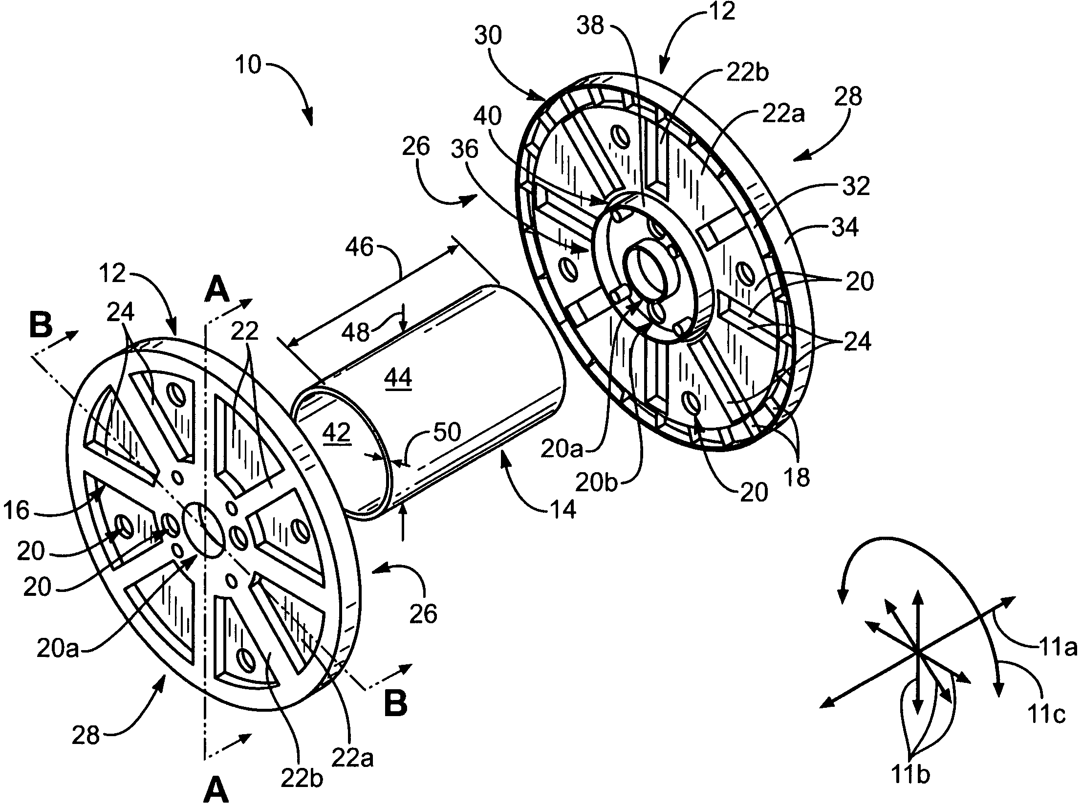
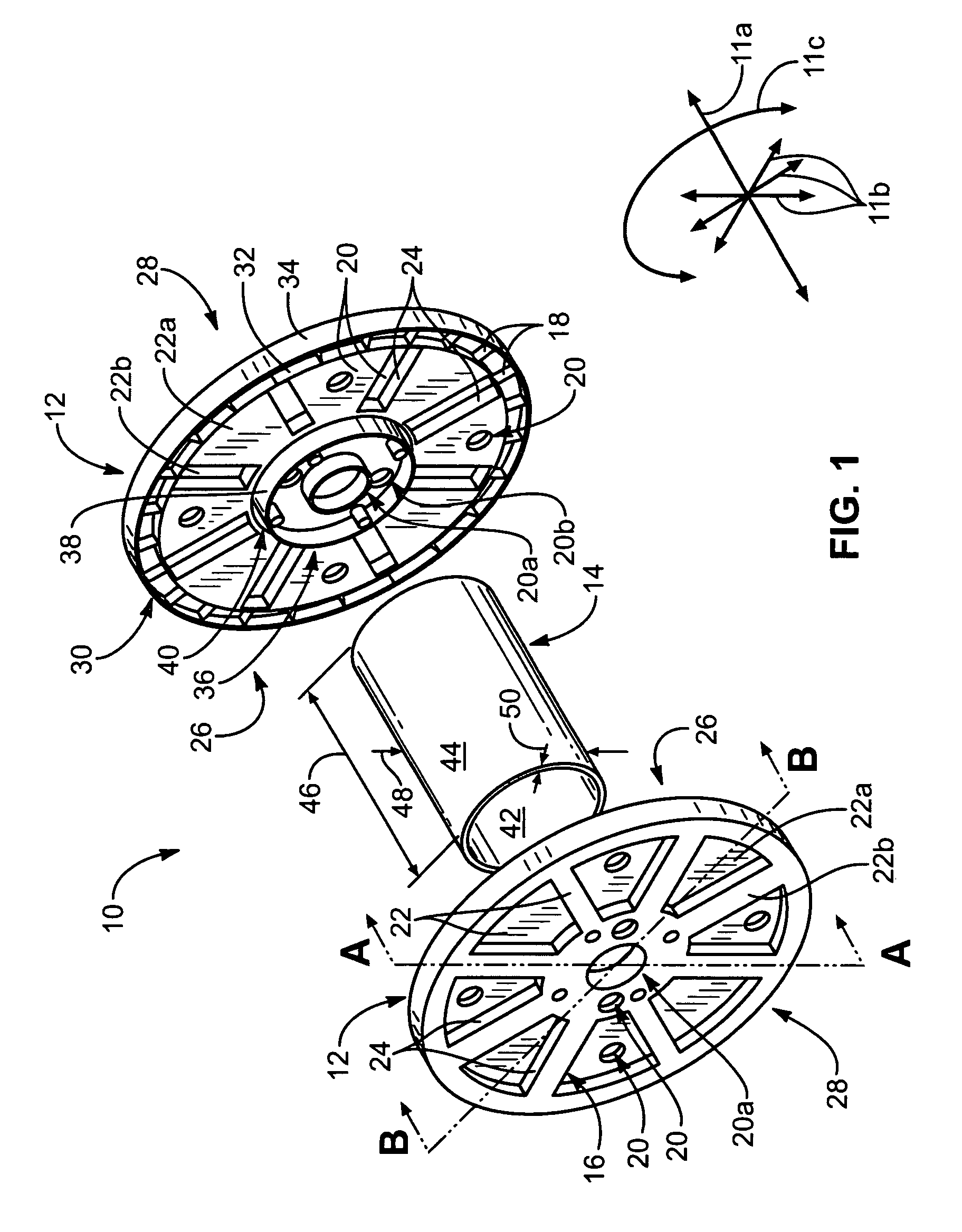
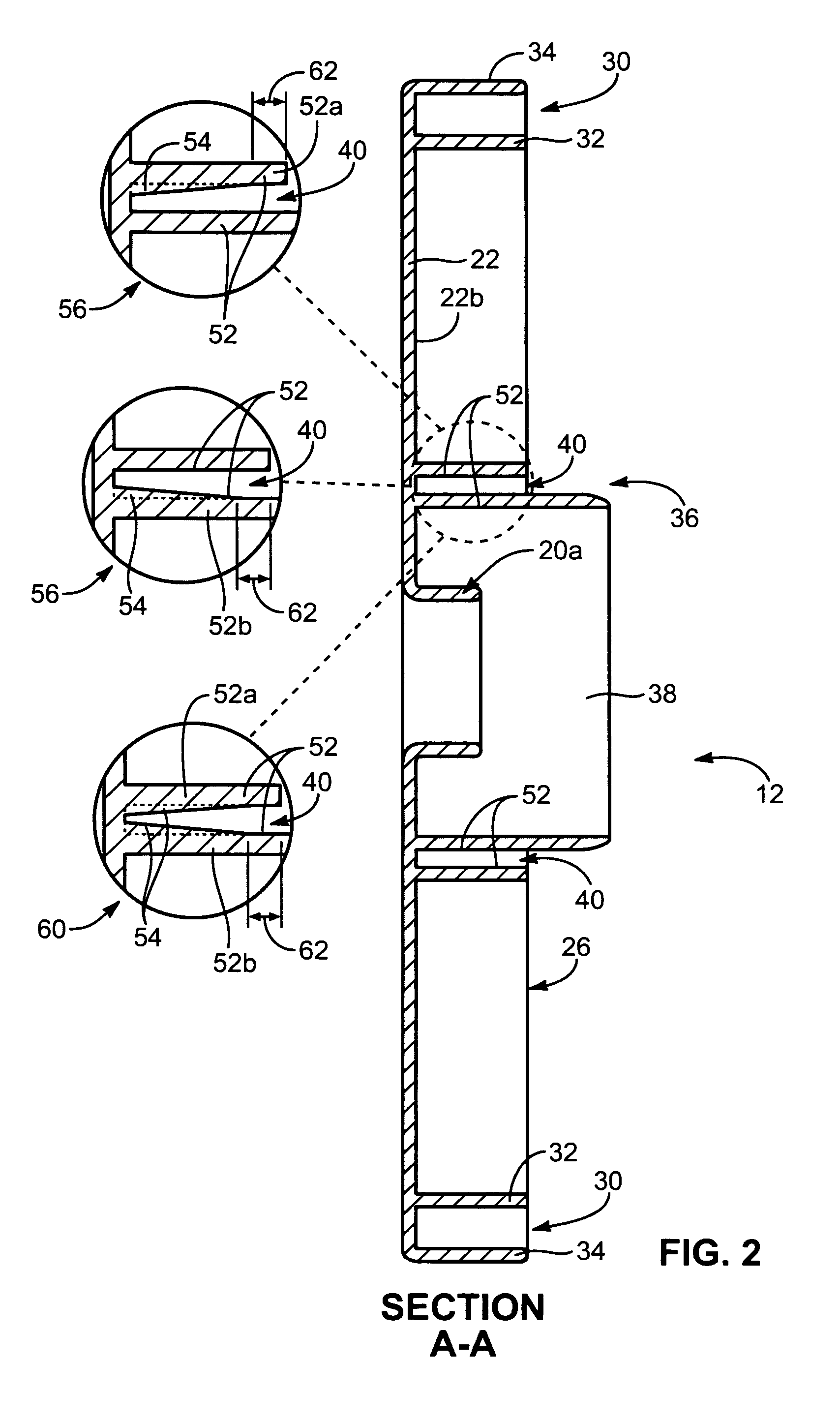
[0045]It will be readily understood that the components of the present invention, as generally described and illustrated in the drawings herein, could be arranged and designed in a wide variety of different configurations. Thus, the following more detailed description of the embodiments of the system and method of the present invention, as represented in the drawings, is not intended to limit the scope of the invention, as claimed, but is merely representative of various embodiments of apparatus and methods in accordance with the invention. The illustrated embodiments of the invention will be best understood by reference to the drawings, wherein like parts are designated by like numerals throughout.

[0046]In certain embodiments, an apparatus and method in accordance with the invention may involve structural systems formed of two or more individual parts made using polymeric resins of differing grades. For example, one part may be made from an injection grade polymeric resin, while an...


PUM

PropertyMeasurementUnit
timeaaaaaaaaaa
diameteraaaaaaaaaa
diameteraaaaaaaaaa

Abstract

A method for welding parts formed of polymeric resins having different melt-index grades. The method may include the steps of selecting a tube formed of a first thermoplastic in an extrusion process, selecting a first flange formed of a second thermoplastic in an injection molding process and having a containment region sized to receive an end of the tube, inserting an end of the tube within the containment region of the first flange, and welding the tube to the flange by inducing relative rotation between the flange and the tube. The containment region may have a depth more than two times the wall thickness of the tube. Moreover, the containment region may maintain its shape and support friction pressure on a significant portion of melted material within the weld zone, so the material may continue to generate heat and conduct the same to the less easily melted material.

Description

RELATED APPLICATIONS[0001]This application claims the benefit of U.S. Provisional Patent Application Ser. No. 60 / 580,567, filed Jun. 17, 2004 for CROSS-GRADE SPIN WELDING APPARATUS AND METHOD.BACKGROUND[0002]1. The Field of the Invention[0003]This invention relates to joining plastics and, more particularly, to novel systems and methods for joining plastics of dissimilar grade.[0004]2. The Background Art[0005]In spin welding two parts together, also known as rotary friction welding, one part is typically held stationary, while the other part is rotated in relative rotation thereagainst. The heat generated by the friction between the two parts causes portions of both to melt. Accordingly, once relative rotation between the parts ceases, the melted material cool sand solidifies, leaving the parts chemically bonded together.[0006]It has been discovered that the processes for friction welding or spin welding of polymeric resins of similar grade operate within certain parameters. For exa...

Claims


Application Information

Patent Timeline
Patent Type & Authority Patents(United States)
IPC IPC(8): B32B37/00B29C65/00B29C65/06
CPCB29C65/0672B29C66/12441B29C66/73115B29C66/73116B29C66/5344B29C66/30223B29K2101/12B29L2031/704B29C65/00B29C66/612B29C66/71B29K2055/02B29K2025/06B29K2023/06
Inventor RIPPLINGER, JACOB F.RIPPLINGER, C. ROBERT
Owner SONOCO DEV INC
Why Eureka
Try Eureka