
Cortical sensing device with pads

a cortical electrode and sensing pad technology, applied in the field of cortical electrode sensing devices, can solve the problems of inconvenient use, poor adaptability, and inability to accurately localize the loci of the cortical electrode, and achieve the effect of preventing injury to the patien

Active Publication Date: 2009-05-19
TECH MEDICAL INSTR
View PDF6 Cites 9 Cited by
  • Summary
  • Abstract
  • Description
  • Claims
  • Application Information

AI Technical Summary

Benefits of technology

The device effectively prevents unintentional movement and penetration, providing a larger contact area with the brain surface, enabling more accurate and reliable monitoring of cortical electrical activity while maintaining ease of placement and safety.

Problems solved by technology

While scalp contacts were customarily used for many years to identify epileptogenic foci, accurate localization of the loci was usually very difficult with the recordings obtained from such contacts.
While the typical cortical strip electrode works fine in many situations, there are applications for which its structure is not well suited.
The typical cortical electrode is, however, not well anchored or held in place at its desired position upon the brain without being sandwiched between the dura and the cerebral cortex.
Nevertheless, movement of the electrode can occur and this movement may even cause inadvertent penetration of the brain.

Method used


Image

  • Cortical sensing device with pads
  • Cortical sensing device with pads
  • Cortical sensing device with pads

Examples


Embodiment Construction

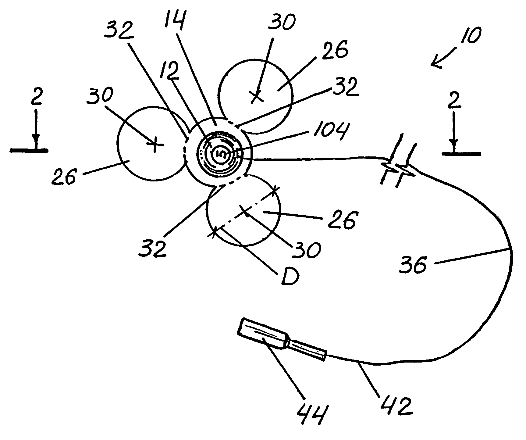
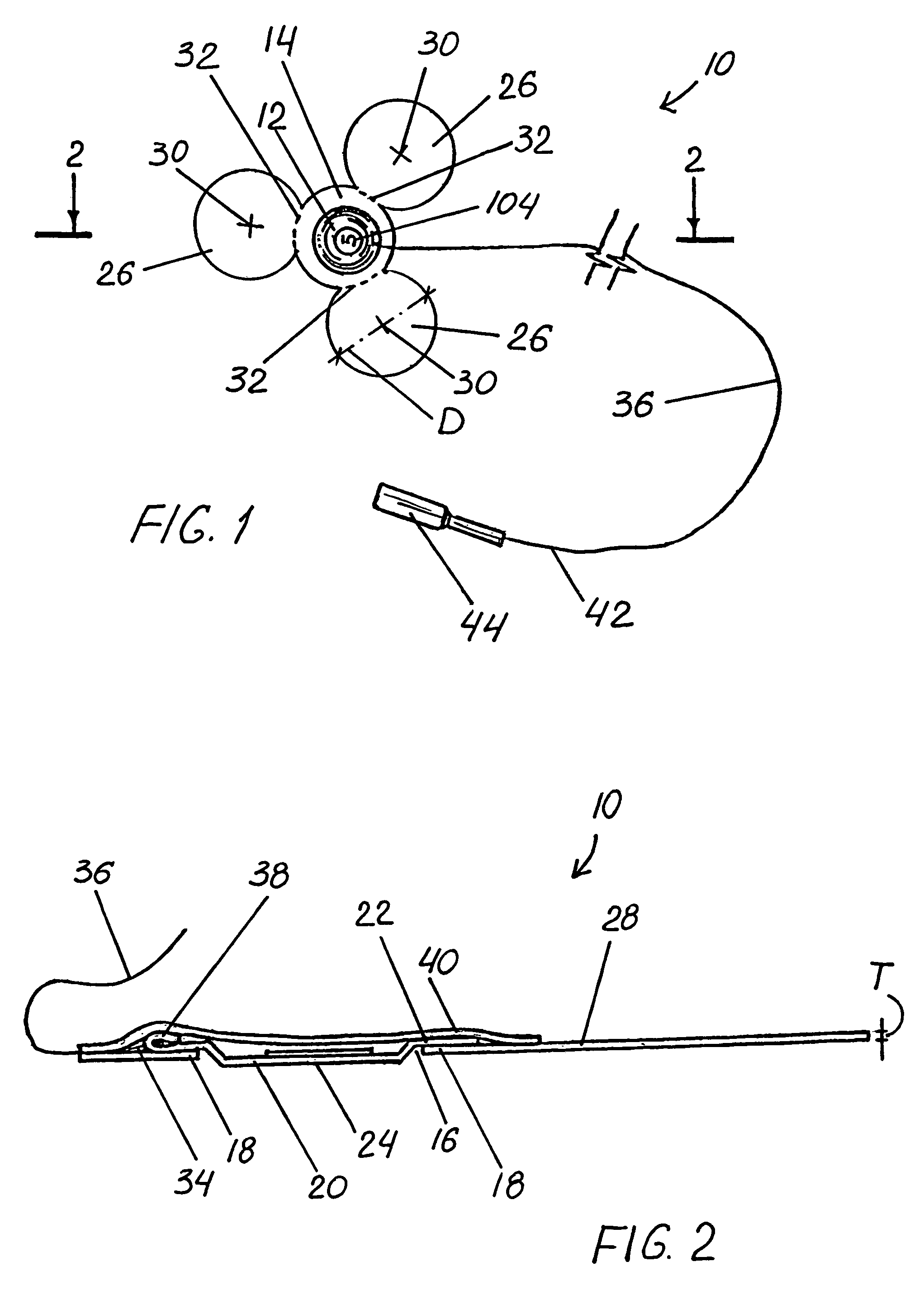
[0031]FIG. 1 is a top view of a cortical sensing device 10 having a preferred embodiment in accordance with this invention. Cortical sensing device 10 includes a sensing element, preferably an electrical contact 12 as shown, secured to circular support member 14. Support member 14 is provided with a circular opening 16 surrounded by a rim 18. Contact 12 has a central disk 20 with support-flange 22 extending along the circumference of disk 20. Opening 16 is sized to receive disk 20 in a manner where lower surface 24 of disk 20 can protrude downward from and not be covered by support member 14. Disk 20 protrudes no more than 0.025 in. through opening 16 and, in certain preferred embodiments, lower surface 24 is flush with support member 14. Support-flange 22 is preferably adhesively sealed along its length to rim 18.

[0032]Cortical sensing device 10 is also provided with three substantially similar circular pads 26 extending outward from support member 14. Support member 14 and pads 26...


PUM


Abstract

A cortical sensing device is provided that includes a sensing element and at least one pad attached adjacent to a support member. The pad is substantially thin and made from flexibly-conformable material to accurately and safely place the sensing device upon the brain surface. Contact between the lower surface of the pad and the brain surface anchors the sensing element at a desired position against unintentional movement. The sensing device preferably has three circular pads equidistant from one another. A method to position a cortical sensing device upon a brain surface is also disclosed comprising the steps of providing a cortical sensing device having a sensing element and three dielectric pads attached to a support dielectric member where the member and the pads are thin and flexibly-conformable, placing the sensing device upon the brain surface at a desired position for sensing brain activity, and allowing the pads to conform to the brain surface so that interaction therebetween prevents movement of the sensing element along the brain surface.

Description

FIELD OF THE INVENTION[0001]This invention is related generally to intracranial sensing devices and, more particularly, to cortical sensing devices.BACKGROUND OF THE INVENTION[0002]Surgical removal of epileptogenic brain is indicated for the treatment of many medically refractory focal seizure disorders. Such surgery demands a high degree of accuracy in identifying the epileptogenic foci. Various methods have been used in attempting to determine the location of these foci, and all involve sensing cortical electrical activity using electrical contacts applied in various ways.[0003]While scalp contacts were customarily used for many years to identify epileptogenic foci, accurate localization of the loci was usually very difficult with the recordings obtained from such contacts. Therefore, many medical centers in recent years have progressed to using intracranial recording techniques to better define regions of cortical epileptogenicity whereby the safety and effectiveness of epileptog...

Claims


Application Information

Patent Timeline
Patent Type & Authority Patents(United States)
IPC IPC(8): A61B5/04
CPCA61B5/0478A61B2562/164A61B5/291
Inventor PUTZ, DAVID A.SCHNELLBERGER, ALFONS
Owner TECH MEDICAL INSTR
Learn More