Method and apparatus for moving a pallet running on wheels in a travelator or equivalent

a technology of a traveler and a pallet, which is applied in the direction of transportation items, hoisting equipment, loading/unloading vehicle arrangment, etc., can solve the problems of insufficient operation, inability to move such fixed structures from one place to another as required when the traffic needs change is completely impossible, and the operation is not smooth enough. , to achieve the effect of low construction cost, flexible installation location, and cost saving

Inactive Publication Date: 2009-05-26
KONE CORP
View PDF11 Cites 11 Cited by
  • Summary
  • Abstract
  • Description
  • Claims
  • Application Information

AI Technical Summary

Benefits of technology

[0012]Embodiments of the method and apparatus of the invention have the advantage that, due to the low construction, the travelator structure can be mounted directly on its base. The total height of the travelator structure at its lowest can be only a little over the height of two pallets, allowing a space for the returning pallets to pass under the pallets above. In such a solution the base may be, e.g., an asphalt surface or a concrete surface either outdoors or inside a building. The structure does not at all require a pit or corresponding space specially made for it, so the invention provides advantages in terms of economy in cost, as well as flexibility in location of installation. In addition, if necessary, the travelator structure of the invention can be moved to a new place with minor modification work and at a low modification cost. A further advantage is that the invention enables a light structure such that the floor under the travelator forms the final stiffening of the structure.
[0013]Yet another advantage is that the pallet will not get jammed at any stage at its dead center, so the structure works reliably and no operating disturbances due to jamming occur. Therefore, the travelator can be constructed using quite long pallets, even as long as over one meter in the direction of motion. In practice, for reasons of manufacture and installation and to avoid very long travelator end portions, a preferable pallet length in the direction of motion is between 350 mm and 700 mm. An advantageous pallet length is about 500 mm, which allows the travelator end portions to be made to a reasonable size and the pallet to be manufactured by extruding the pallet body as a unitary piece while the weight of the pallet remains relatively low in view of installation work.
[0014]An additional advantage is that, when the pallet is to be transferred from one level to the other during a direction change, it is always moved by the current rearward wheels, in other words, alternately by “front” wheels and by “rear” wheels. This, combined with the fact that both the pallet and the track have a mirror image-like structure in the longitudinal direction of the track, enables a simple construction that allows the pallets to be driven in a clockwise direction as well as in a counter-clockwise direction. Moving the pallets by their wheels also provides the advantage that during direction change the paths of the pallets are precise and, due to the continues grip, the transfer operation is quiet. Besides, no extra clatter occurs during the change of direction of the pallets because the idler that moves the pallets and functions as a supporting element is in contact with the bearing wheels of the pallet which have a soft surface layer. Clatter and other extra noise are also inhibited by having the idler so positioned that it will meet the bearing wheel in an advantageous position. Such positioning of the idler also improves the reliability of the conveyor as a whole and reduces the risk of disturbance. The positioning of the idler is preferably accomplished by using a positioning device attached to the idler. Between contacts of the idler with the wheels of the pallet, i.e., the bearing wheels, the positioning device forces the idler into a position in which the idler is ready to receive the approaching bearing wheel into a specific area provided on the idler and designed for bearing wheel contact, this area being referred to as the engaging area. In the castellated wheel-type idler described hereinafter, the engaging area is the bay between the castellations of the castellated wheel. “Between bearing wheel contacts” in this context means a situation where the bearing wheel of a pallet whose direction of motion is being changed does not determine the position of the idler by contact with it.

Problems solved by technology

A drawback with this type of travelator construction is that they require heavy and fixed structures in the floor of the space around them, which is why they have to be taken into account at the time when the building is being designed.
A further drawback is that moving such fixed structures from one place to another as required when the traffic needs change is completely impossible.
One of the problems with such a prior art solution is that the pallets are turned around at the ends of the track, requiring the space where the pallets are turned to have a depth at least equal to the length of the pallet.
In practice, however, the depth is about 1.5 to 2 times the length of the pallet because, otherwise, the operation will not be smooth enough.
However, the solution according to this patent document involves the problem that there are so-called dead centers at the end points of the track where the position of the pallet is not completely precisely defined.
For this reason, the pallet may get jammed at the dead center, in which case the whole apparatus will stop due to the operating disturbance and may even be damaged.
The risk of pallets getting jammed is increased by the running clearances, non-ideal track design and wear of the mechanism.

Method used


Image

  • Method and apparatus for moving a pallet running on wheels in a travelator or equivalent
  • Method and apparatus for moving a pallet running on wheels in a travelator or equivalent
  • Method and apparatus for moving a pallet running on wheels in a travelator or equivalent

Examples


Embodiment Construction

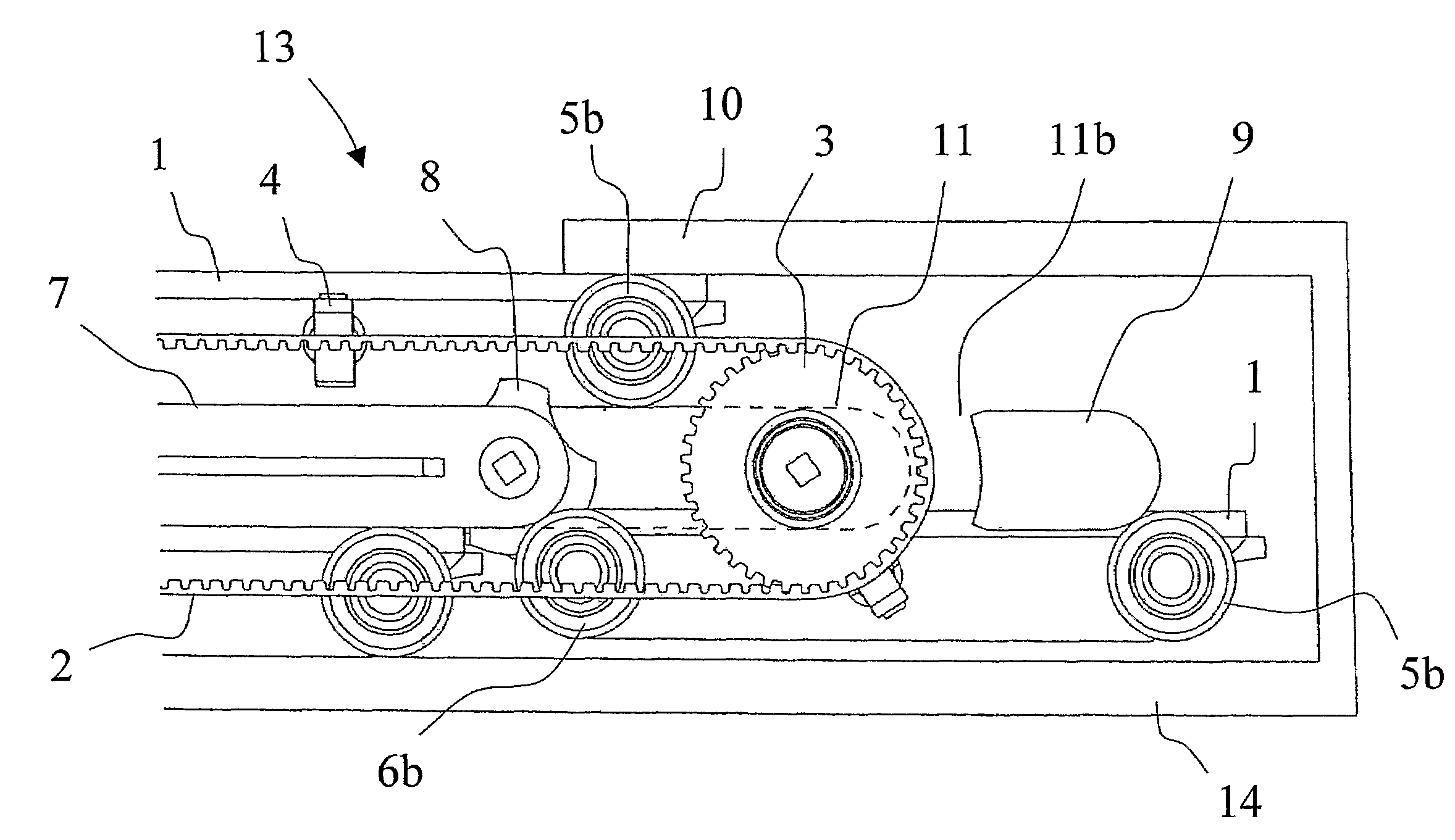
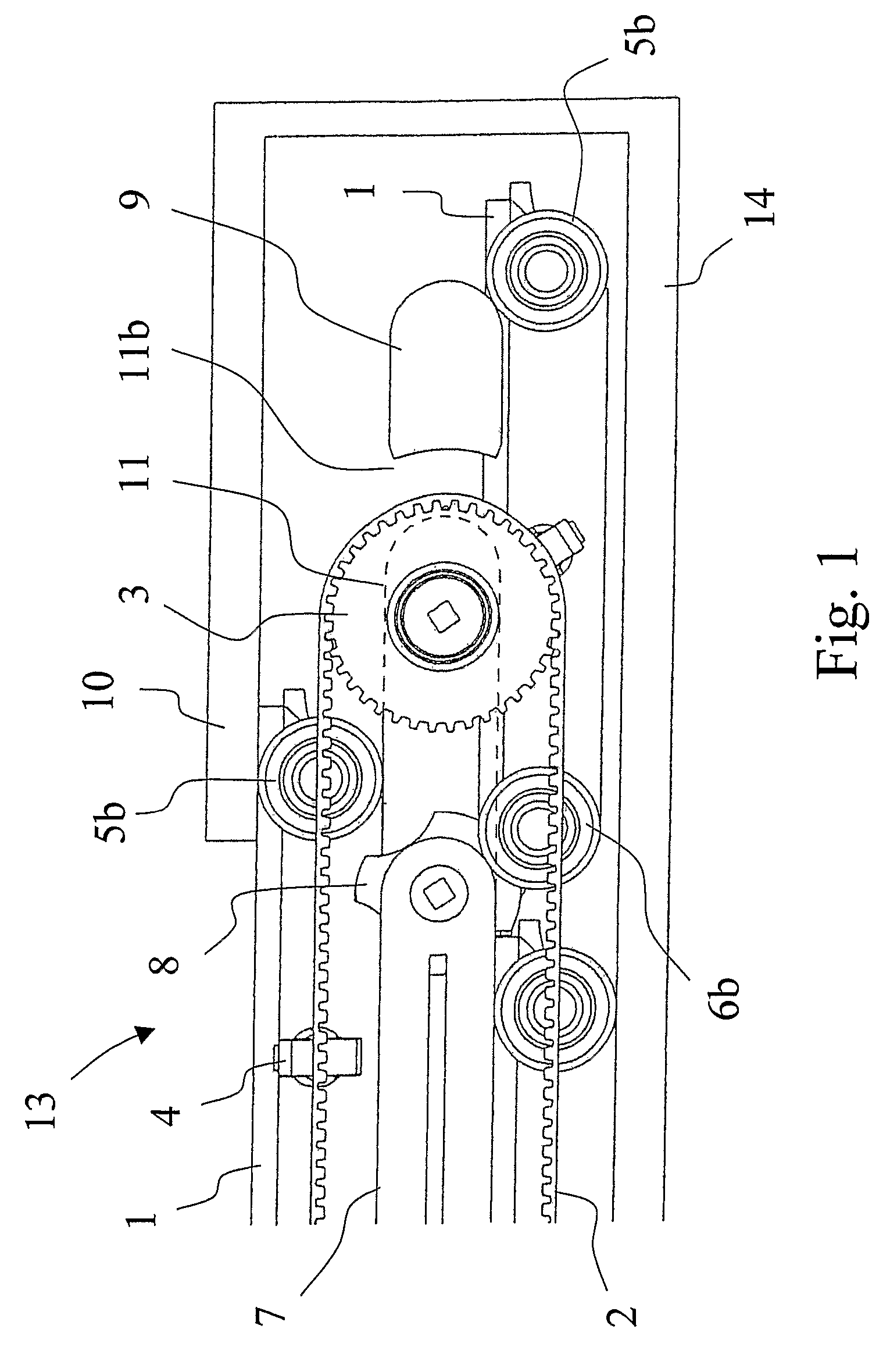
[0023]Referring to FIG. 1, an embodiment of a travelator structure 13 of the invention comprises a frame structure 14, the function of which is to hold the equipment together and transmit the forces to the base under it. Inside the frame structure is a pallet track, on the upper surface of which the passengers stand. In addition, the travelator structure comprises at least a pallet track drive machine with a drive sprocket 3 and a cogged belt 2 as well as handrails and the drive machine for driving them.

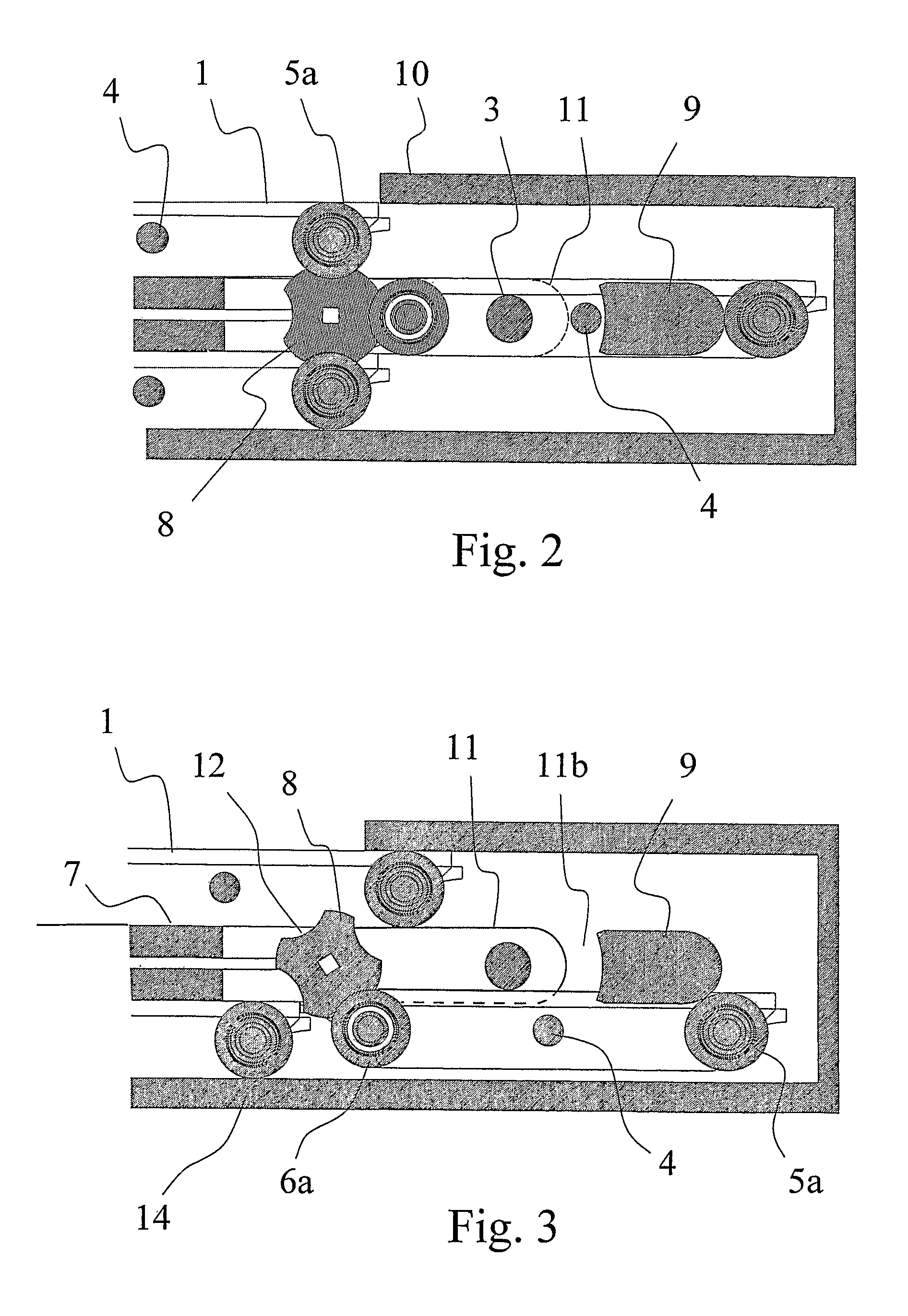
[0024]The pallet track consists of separate pallets 1 having wheels. The front wheels 5a and 5b of each pallet are located at the forward corners of the pallet relative to the normal direction of motion of the travelator; likewise, the rear wheels 6a and 6b are located at the rearward corners of the pallet. As shown in FIG. 4, the front wheel 5a at the forward corner is offset outwardly by a predetermined distance from the pallet with respect to the corresponding rear wheel 6a on the...


PUM


Abstract

A method for changing the direction of motion of a pallet moving on wheels at an end of a travelator. The method comprises moving the pallet in a traveling direction at a first level, positioning a supporting element in alignment to receive a wheel of the pallet using a positioning device, positively guiding a trailing end of the pallet from the first level to a second level different than the first level by supporting the wheel of the pallet with the supporting element, and moving the pallet in a return direction at the second level. The pallet maintains a substantially constant orientation during the change of direction of motion.

Description

CROSS-REFERENCE TO RELATED APPLICATIONS[0001]This application is the National Stage of International Application No. PCT / FI2005 / 000260, filed Jun. 6, 2005, which claims the priority benefit of Application No. FI20040950, filed in Finland on Jul. 7, 2004.BACKGROUND[0002]1. Technical Field[0003]The present invention relates to a method and apparatus for changing the direction of motion of a pallet moving on wheels at the end of a travelator or equivalent.[0004]2. Related Art[0005]Like escalators, travelators are conveying devices primarily designed to move people and their goods. They differ from escalators, e.g., in that they are often operated in a substantially horizontal orientation or in an orientation somewhat inclined, e.g., typically by about 1-15° relative to their direction of motion. Successive steps or pallets typically form a substantially even and rectilinear conveyor track instead of stair-like steps as in escalators. Instead of successive steps, the travelator may also...

Claims


Application Information

Patent Timeline
Patent Type & Authority Patents(United States)
IPC IPC(8): B66B21/10B65G17/18B66BB66B23/14
CPCB66B23/147
Inventor MUSTALAHTI, JORMAAULANKO, ESKOOSSENDORF, MARC
Owner KONE CORP
Why Eureka
Try Eureka