
Work stand

a technology for supporting stands and work, applied in the field of work supporting stands, can solve the problems of excessive free-play, no stability, interference of excessive free-play, etc., and achieve the effects of eliminating free-play, facilitating the carrying of the stand, and facilitating the displacement of the legs

Inactive Publication Date: 2009-05-26
EMERSON ELECTRIC CO
View PDF17 Cites 13 Cited by
  • Summary
  • Abstract
  • Description
  • Claims
  • Application Information

AI Technical Summary

Benefits of technology

Facilitates easy leg transition between positions, enhances stability and prevents unintended leg displacement during storage and use, improving transportation and storage capabilities.

Problems solved by technology

In this respect, for example, physically displacing the legs of the stand between the extended and retracted positions thereof is difficult and cumbersome and, in the retracted positions of the legs, there is no stability against unintended displacement of the legs toward the extended position if, for example, the stand is inclined in the direction promoting displacement of the legs relative to the base and toward the extended positions thereof.
Still further, there is excessive free-play as the result of wear and / or an accumulation of manufacturing tolerances between the legs, base and other parts of the stands mentioned above, and the excessive free-play interferes with a smooth displacement of the legs and transition of the component parts of the stand between the extended and retracted positions of the legs.

Method used


Image

  • Work stand
  • Work stand
  • Work stand

Examples


Embodiment Construction

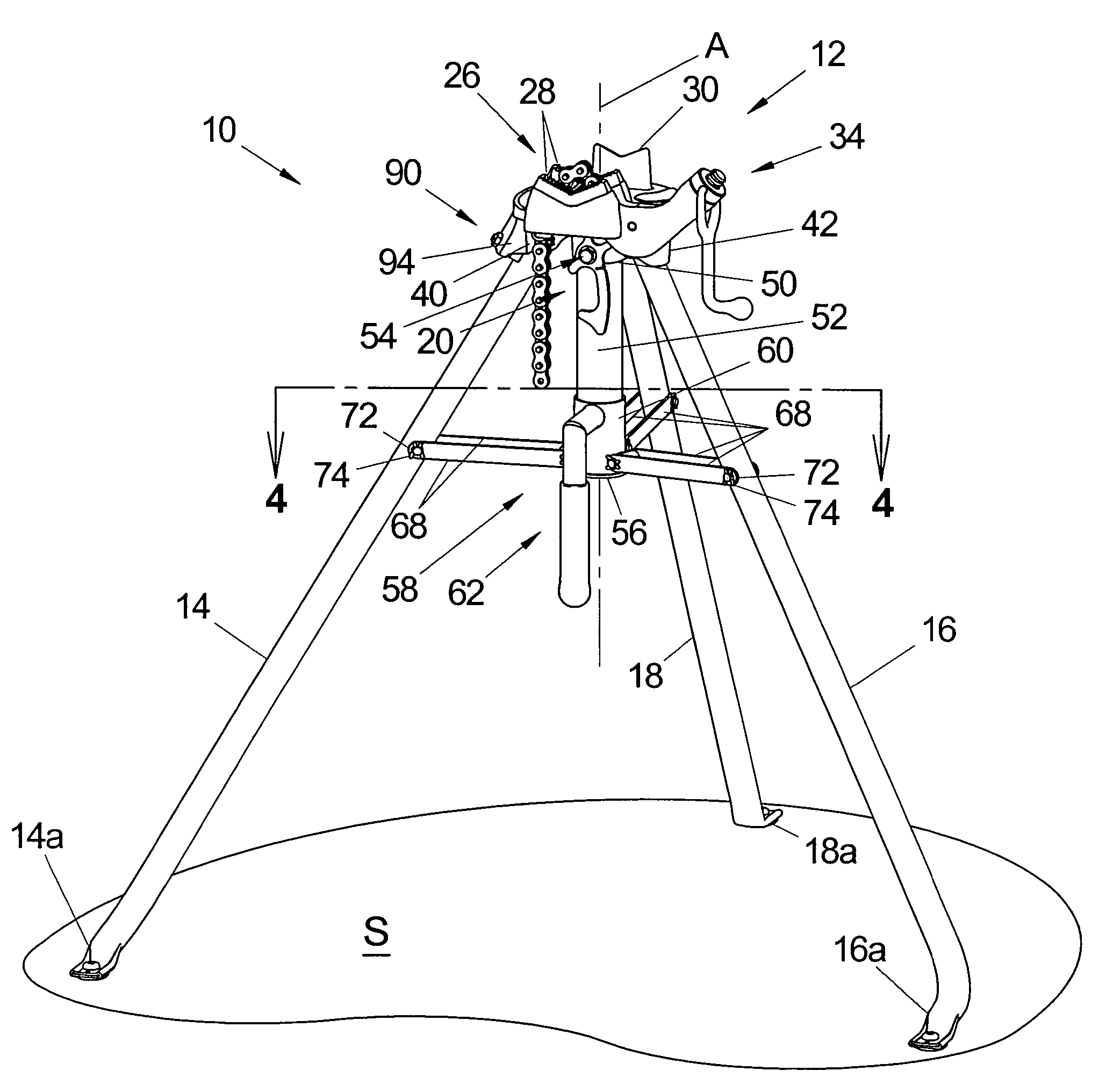
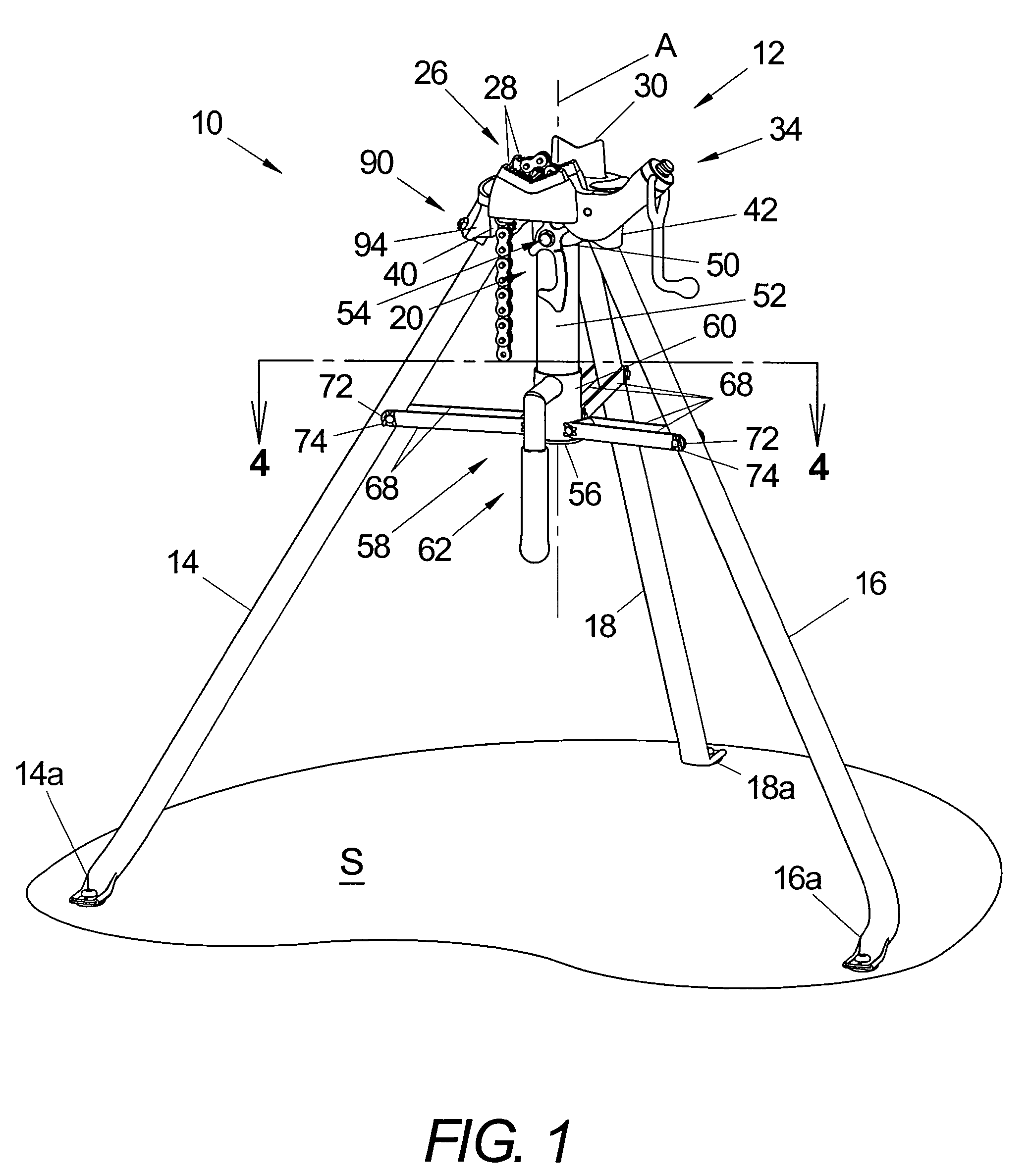
[0020]Referring now in greater detail to the drawings, wherein the showing are for the purpose of illustrating a preferred embodiment of the invention only, and not for the purpose of limiting the invention, a stand 10 in accordance with the present invention comprises a base 12, a pair of front legs 14 and 16, and a rear leg 18, which legs are tubular and are pivotally mounted on base 12 as set forth more fully hereinafter for displacement between extended and retracted or folded positions relative to base 12. In the extended position of the legs, as shown in FIG. 1, the stand is adapted to be supported on an underlying surface S for use. As set forth more fully hereinafter, when the legs are in the retracted positions thereof they are adapted to be captured by a latch mechanism 20 on the stand to facilitate transportation and storage thereof.

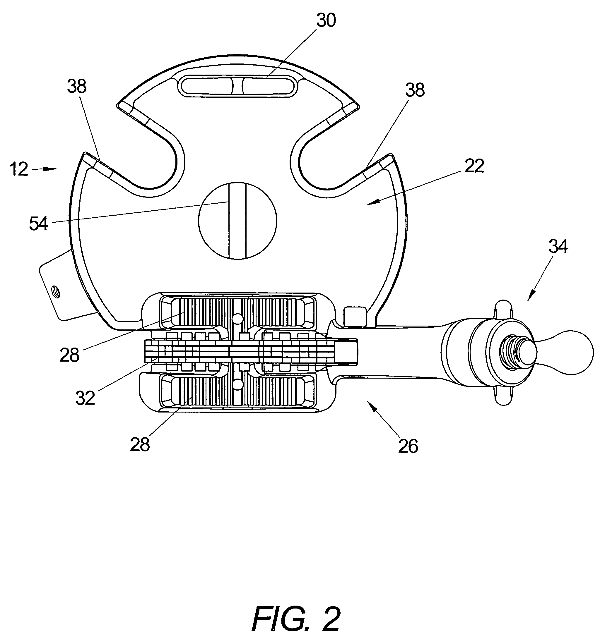
[0021]As best seen in FIGS. 2 and 3 of the drawing, base 12 is preferably a unitary iron casting having top and bottom sides 22 and 24, respe...


PUM


Abstract

A work stand comprises a base having top and bottom sides and a tubular support member extending downwardly from said bottom side. Three legs are spaced apart about the support member and have upper ends pivotally attached to the base and lower ends below the support member for engaging an underlying surface to support the base above said surface. A collar is slidable on the tubular support member between upper and lower positions relative to the base, and links between the collar and legs provide for displacing the legs between extended and retracted positions relative to the support member when the collar is moved along the support member. A handle is mounted on the sleeve for displacing the sleeve and thus the legs between the extended and retracted positions thereof and for carrying the stand in the retracted position of the legs. A latch on the base and a keeper provided by the handle interengage in the retracted position of the legs to releasably hold the legs in the retracted position.

Description

BACKGROUND OF THE INVENTION[0001]This invention relates to the art of work supporting stands and, more particularly, to improvements in a foldable and transportable tripod stand for supporting work pieces such as pipes.[0002]A tripod-type work stand of the character to which the present invention relates in general is shown, for example, in U.S. Pat. No. 2,831,583 to Wright, et al. This stand comprises a base for supporting a vise, and three legs pivotally attached to the base for displacement between extended and retracted positions relative thereto. In the extended positions the legs are in a tripod configuration for supporting the base above an underlying surface, and in the retracted positions the legs are generally parallel to one another to facilitate storage and transportation of the stand. An assembly of pivotally interconnected plates is stored between the legs when the latter are in the retracted positions and, in the extended positions of the legs, the plate assembly plac...

Claims


Application Information

Patent Timeline
Patent Type & Authority Patents(United States)
IPC IPC(8): F16M11/00
CPCB25H1/00
Inventor PUTRE, MICHAEL H.MORRIS, STEVEN K.GALLAGHER, MICHAEL P.
Owner EMERSON ELECTRIC CO
Learn More