Fuel system and method of reducing emission

a fuel system and emission reduction technology, applied in the direction of hot gas positive displacement engine plants, machines/engines, combination devices, etc., can solve the problems of undesirable emissions, reduced formation, and unsatisfactory treatment of undesirable emissions by conventional combustion engines or combustors, so as to reduce the emissions of undesirable combustion products, good combustor operability, good operability

Inactive Publication Date: 2009-05-26
UNITED TECH CORP
View PDF11 Cites 19 Cited by
  • Summary
  • Abstract
  • Description
  • Claims
  • Application Information

AI Technical Summary

Benefits of technology

[0009]An exemplary method of reducing emissions of an undesirable combustion product according to the present invention includes vaporizing at least a portion of a liquid fuel to produce vaporized fuel and the mixing of vaporized fuel with oxidizer to produce a mixture of vaporized fuel and oxidizer. The mixture of vaporized fuel and oxidizer is then reacted in a combustor. The flame temperature of the vaporized fuel and oxidizer mixture is lower than that of the direct combustion in the oxidizer of the liquid fuel from which the vaporized fuel was produced. This reduces the formation of at least a portion of undesirable combustion products. Local injection of liquid fuel into the combustor may be used to “pilot” the combustion process in order to insure good combustor operability. In addition, the ratio of liquid fuel flow rate to vapor fuel flow rate may be adjusted in order to ensure good operability. The fuel injection process is managed by a controller, which controls the distribution of both vapor and liquid fuel to one or a multiplicity of fuel injectors and / or mixers. This distribution of fuel flows and the ratio of liquid fuel flow rate to vapor fuel flow rate are the key control parameters, and can be varied by the controller in order to minimize a cost function that accounts for both pollutant emissions and operability. This controller may operate in an “open-loop” or “set-point” fashion, in which the fuel distribution and flow rate ratios are determined a priori, or it may operate in a “closed-loop” or “active” fashion, in which the fuel distribution and flow rate ratios are determined based on information received by a sensor or sensors that measure the emissions and operability of the combustor.

Problems solved by technology

Disadvantageously, the combustion may result in the production of undesirable emissions, such as oxides of nitrogen (NOx), carbon monoxide (CO), uncombusted fuel (UHC), and carbonaceous soot.
Conventional combustion engines or combustors have not satisfactorily addressed the undesirable emissions.
This may reduce formation of some of the emissions, however, it increases the amount of uncombusted fuel (i.e., reduces combustion efficiency).
The increase in uncombusted fuel may negate a significant portion of the benefit accrued from the reduction in the formation of the emissions.
Combustors with poor operability may experience “blow-out” events in which the flame is extinguished.
Poor operability may also lead to large combustor pressure oscillations which can cause noise and vibration problems and decrease combustor durability.

Method used


Image

  • Fuel system and method of reducing emission
  • Fuel system and method of reducing emission
  • Fuel system and method of reducing emission

Examples


Embodiment Construction

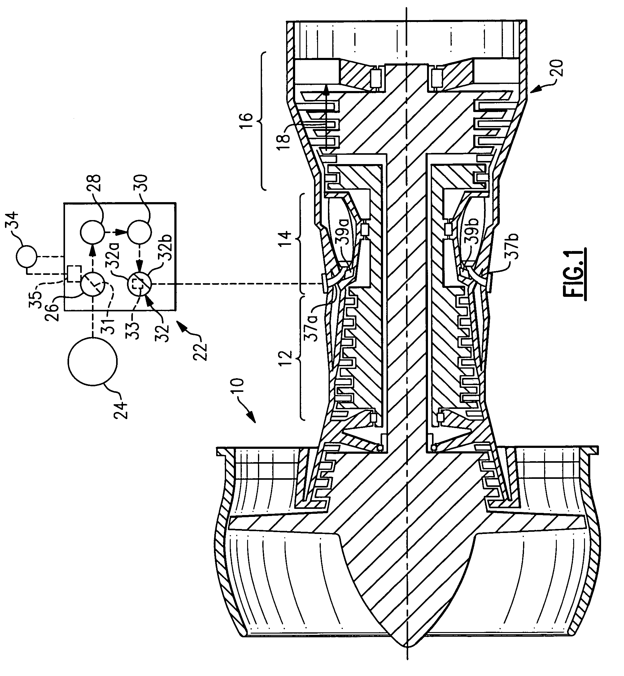
[0016]FIG. 1 illustrates selected portions of an example combustion engine assembly 10, such as a gas turbine engine for an aircraft. In this example, the combustion engine assembly 10 includes a compressor 12, a combustor 14, and a turbine 16. The combustion engine assembly 10 operates in a known manner, feeding compressed air or oxidizer from the compressor 12 to the combustor 14. The compressed air or oxidizer is mixed with fuel and react to produce a flow of hot gases 18. The turbine 16 transforms the flow of hot gases 18 into mechanical energy to drive the compressor 12. An exhaust nozzle 20 directs the hot gases out of the combustion engine assembly 10 to provide thrust to the aircraft or other vehicle.

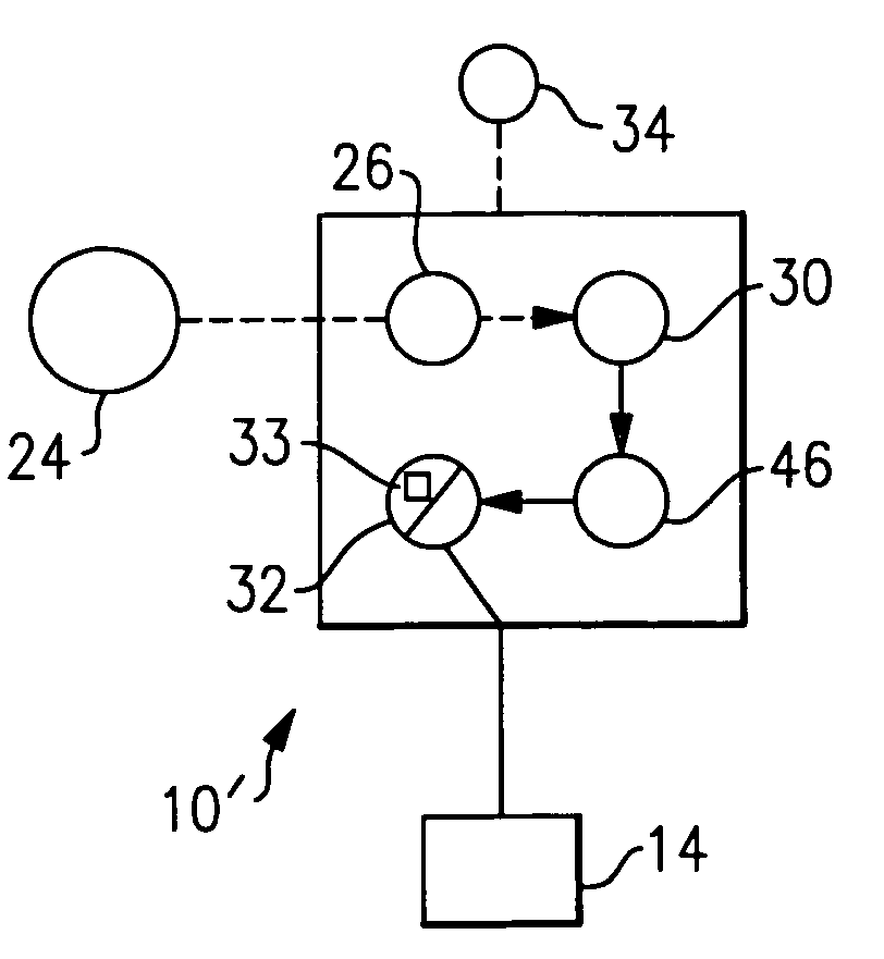
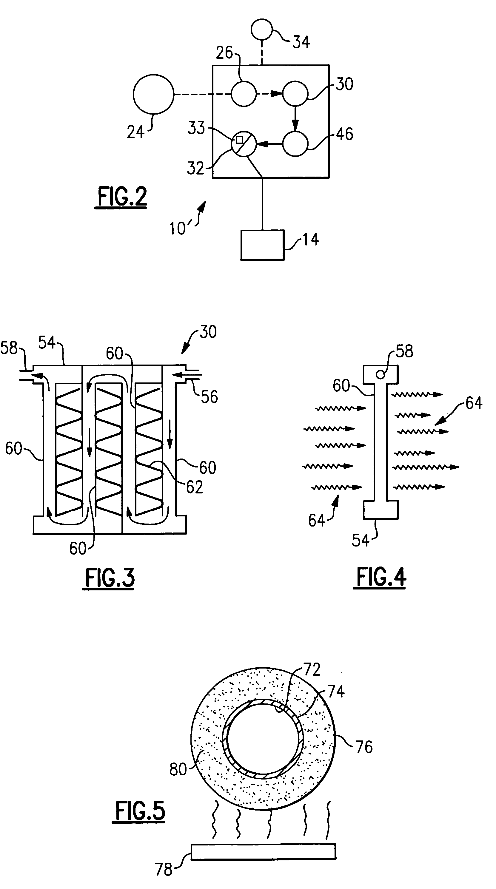
[0017]A fuel system 22 supplies fuel to the combustor 14. A fuel storage 24 holds liquid fuel. The liquid fuel is received by a fuel deoxygenator 26 from the fuel storage 24 with or without the assistance from a fuel pump. The fuel deoxygenator 26 removes or reduces dissolved ox...


PUM

PropertyMeasurementUnit
temperatureaaaaaaaaaa

Abstract

A fuel system includes a fuel deoxygenator for removing oxygen from a liquid fuel. A vaporizer is in fluid communication with the fuel deoxygenator. The vaporizer vaporizes at least a portion of the liquid fuel to produce vaporized fuel. At least a portion of the vaporized fuel pre-mixes with oxidizer to reduce formation of undesirable emissions.

Description

BACKGROUND OF THE INVENTION[0001]This invention relates to combustion engines or combustors and, more particularly, to a fuel system arrangement for reducing undesirable emissions from combustion engines or combustors.[0002]Conventional liquid-fueled combustion engines or combustors typically include a fuel system that supplies liquid fuel to a combustor. The liquid fuel reacts with oxidizer or oxidizers to produce a rapidly expanding gas that moves a piston or turbine blades, for example, to propel a vehicle or to produce heat for other applications. Disadvantageously, the combustion may result in the production of undesirable emissions, such as oxides of nitrogen (NOx), carbon monoxide (CO), uncombusted fuel (UHC), and carbonaceous soot.[0003]Conventional combustion engines or combustors have not satisfactorily addressed the undesirable emissions. Many conventional combustion engine assemblies seek to reduce emissions by more efficiently combusting the liquid fuel in compressed ai...

Claims


Application Information

Patent Timeline
Patent Type & Authority Patents(United States)
IPC IPC(8): B01D53/22F23D11/44
CPCB01B1/005B01D19/0031B01D19/0063B01D19/0073F02C3/24F02C7/224F23K5/08F23K2900/05082F02C7/22F02C3/28
Inventor CHEN, ALEXANDER GCOHEN, JEFFREY M.
Owner UNITED TECH CORP
Why Eureka
Try Eureka