
Electrical control panel preferably for height adjustable tables

a technology of electric control panel and height adjustable table, which is applied in the direction of adjustable height tables, hinges, applications, etc., can solve the problems of inexpedient position of the protruding edge of the tabletop, and inability to provide it at a location where it is liable to be damaged

Inactive Publication Date: 2009-05-26
LINAK AS
View PDF4 Cites 40 Cited by
  • Summary
  • Abstract
  • Description
  • Claims
  • Application Information

AI Technical Summary

Benefits of technology

[0006]The object is achieved according to the invention in that the hinge is formed with a rotary shaft on one part and a bearing with a cylindrical face on the other part, said hinge being formed with retaining means such that the keyboard part may assume various angular positions relative to the mounting part, said retaining means exerting a retaining force in the hinge which is greater than the necessary operative pressure on the operating keys, but smaller than the force necessary to move the keyboard part manually between the various angular positions. The keyboard part may thus be adjusted to an angular position convenient to the user, while the part yields to unintentional impacts and blows. In this respect, it is expedient to make at least one end, preferably both ends, of the keyboard part, inclined or curved, whereby the keyboard part rotates away more easily when it hits an obstacle with this edge.

Problems solved by technology

The arrangement of the operating panel causes problems, however, as it should preferably be easy to operate, and on the other hand it must not be provided at a location where it is liable to be damaged.
A position where it protrudes beyond the tabletop is inexpedient, since it is hereby liable to be damaged both during storage, transport and movement.
A position on or mounting in the tabletop has also been found to be inexpedient, since the operating panel quickly gets covered by objects that are left on the table.

Method used


Image

  • Electrical control panel preferably for height adjustable tables
  • Electrical control panel preferably for height adjustable tables
  • Electrical control panel preferably for height adjustable tables

Examples


Embodiment Construction

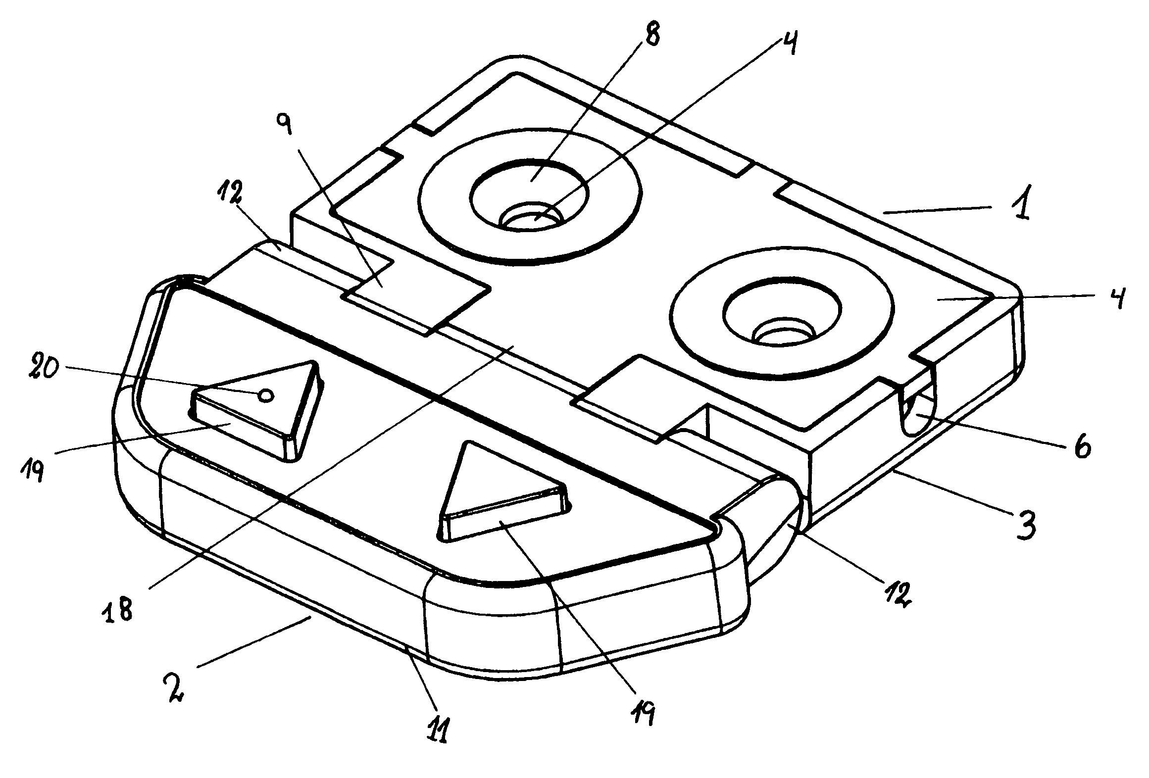
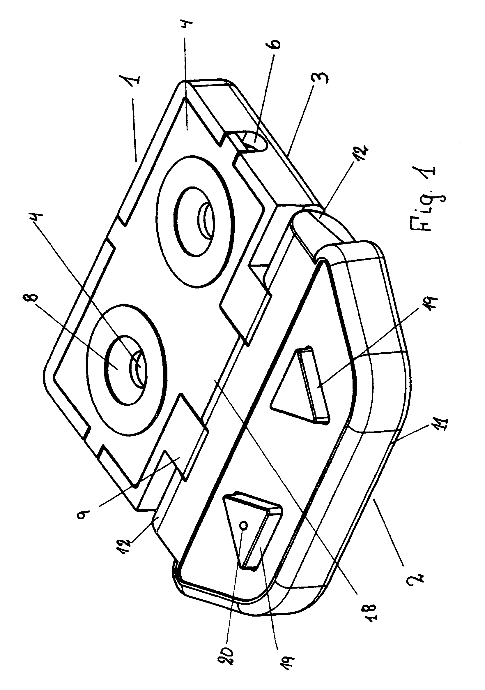
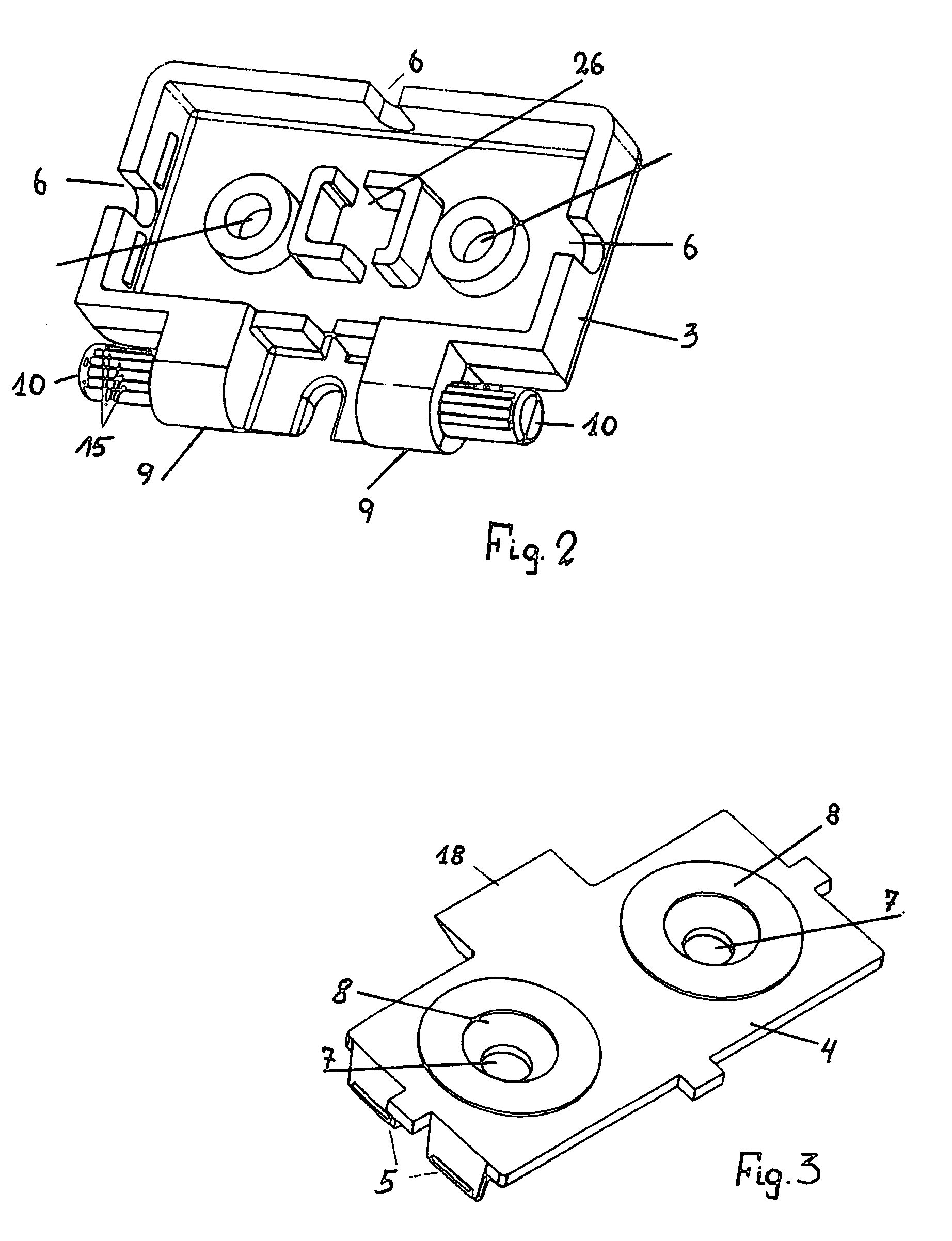
[0020]The operating panel comprises a mounting part 1, called mounting part intended for mounting on the table in the following, and a keyboard part 2, called the keyboard part in the following. The mounting part 1 consists of a flat box 3 which may be closed by a cover 4 retained by snap locks on legs 5. A recess 6 is formed in the three sides for selective guidance of a cable which is passed through a tensile relief 26 consisting of a square tower having two openings which are mutually offset and through which the cable is inserted. Two screw holes 7, defined by a ring wall, extend through the box, said screw holes terminating on the lower side of the box as well as on the upper side of the cover 4 in a countersink 8 for a screw head.

[0021]One long side of the box 3 has two protruding brackets 9 which are cylindrically rounded forwardly. On the sides of the brackets facing away from each other there is a stub shaft 10, and these two together form a rotary shaft for the keyboard pa...


PUM


Abstract

An electrical operating panel, in particular for height-adjustable tables equipped with actuators or lifting columns driven by an electric motor. The panel has a first part (1) intended for fixed mounting of the panel and a second part (2) with operating keys (19) for activating electrical switches. The two parts are hinged together, and the hinge is formed with a rotary shaft (10) on the no part and a bearing with a cylindrical face (13) on the other part and formed with interengaging projections (16) and depressions (15) such that the second part may assume various angular positions relative to the first part, the force between projections and depressions bearing greater than the necessary operative pressure on the operating keys, but smaller than the force necessary to manually move the second part between the various angular positions. The panel is of simple structure and easy to mount and use. The users may easily set the keyboard part in the desired angular position. Furthermore, the panel yields so that it is not damaged in case of collision with an object.

Description

BACKGROUND OF THE INVENTION[0001]1. Field of the Invention[0002]The present invention relates to an electrical control panel, in particular for height adjustable articles of furniture, such as height-adjustable tables equipped with actuators or lifting columns driven by an electric motor, the panel including a mounting part intended for firm fixed mounting of the panel and a keyboard part having operating keys for activating electrical switches, the two parts being hinged together.[0003]2. The Prior Art[0004]Height-adjustable tables equipped with actuators or lifting columns driven by electric motors are adjusted via an operating panel. The arrangement of the operating panel causes problems, however, as it should preferably be easy to operate, and on the other hand it must not be provided at a location where it is liable to be damaged. A position where it protrudes beyond the tabletop is inexpedient, since it is hereby liable to be damaged both during storage, transport and movement...

Claims


Application Information

Patent Timeline
Patent Type & Authority Patents(United States)
IPC IPC(8): H01H9/00H01H13/00H01H19/04H01H19/08A47B9/00E05D11/08E05D11/10
CPCA47B9/00E05D11/082E05D11/105E05Y2900/20
Inventor NIELSEN, JENS JORGENJACOBSEN, FINNRIIS, MARTIN
Owner LINAK AS
Features
  • Generate Ideas
  • Intellectual Property
  • Life Sciences
  • Materials
  • Tech Scout
  • Unparalleled Data Quality
  • Higher Quality Content
  • 60% Fewer Hallucinations
Learn More