All-optical, continuously tunable, pulse delay generator using wavelength conversion and dispersion

a generator and wavelength conversion technology, applied in the field of continuously tunable optical pulse delay generators, can solve problems such as conceptual complexity, speed of operation, and wavelength of operation, and achieve the effect of eliminating residual pulse distortion

Inactive Publication Date: 2009-05-26
CORNELL RES FOUNDATION INC
View PDF4 Cites 5 Cited by
  • Summary
  • Abstract
  • Description
  • Claims
  • Application Information

AI Technical Summary

Benefits of technology

[0007]The present invention relates to a novel technique for generating variable pulse delays (both positive and negative since the invention can also be used for pulse advancement) that uses one or more linear or nonlinear-optical processes such as cross-phase modulation, cross-gain modulation, self-phase modulation, four-wave mixing or parametric mixing, combined with group-velocity dispersion. The delay is controllable by changing the wavelength and / or power of a control laser. In all embodiments of the invention, the delay is generated by introducing a controllable wavelength shift to a pulse of light, propagating the pulse through a component, such as a dispersive fiber, that generates a wavelength dependent time delay and wavelength shifting again to return the pulse to its original wavelength. Residual pulse distortion can be eliminated by using a compensating fiber or diffraction grating. The change in delay that a pulse experiences is proportional to the wavelength shift that was introduced times the group-velocity dispersion of the dispersive fiber, where the shift can be varied by tuning the wavelength of the pump laser.
[0010]Other notable innovations or key features of the invention include the following: the delay is continuously tunable by changing the wavelength and / or power of the pump laser; the system can generate gain or amplification in addition to delay; as noted above, the system can be configured to generate pulse advancement (i.e. negative delay) as well as delay; the system preserves phase information present in the signal pulse train; the use of large wavelength shifts (1 nm-200 nm) results in large tunable delays such that the delay can be large relative to the initial signal pulse width; and the system complexity is dramatically reduced by using common-path (i.e., Sagnac, or retroreflecting) configurations. The relative pulse delay can be made large (on the order of 1000 nanoseconds) or small (on the order of 10 femtoseconds), depending upon the delay range and sensitivity desired. At the same time, the output signal wavelength is the same as that of the input, and the delay-to-pulse-width ratio can be greater than 1000.

Problems solved by technology

Each of the approaches described above has benefits and drawbacks in terms of maximum delay, accuracy of delay, wavelength of operation, speed of operation, pulse distortion, and conceptual complexity.

Method used


Image

  • All-optical, continuously tunable, pulse delay generator using wavelength conversion and dispersion
  • All-optical, continuously tunable, pulse delay generator using wavelength conversion and dispersion
  • All-optical, continuously tunable, pulse delay generator using wavelength conversion and dispersion

Examples


Embodiment Construction

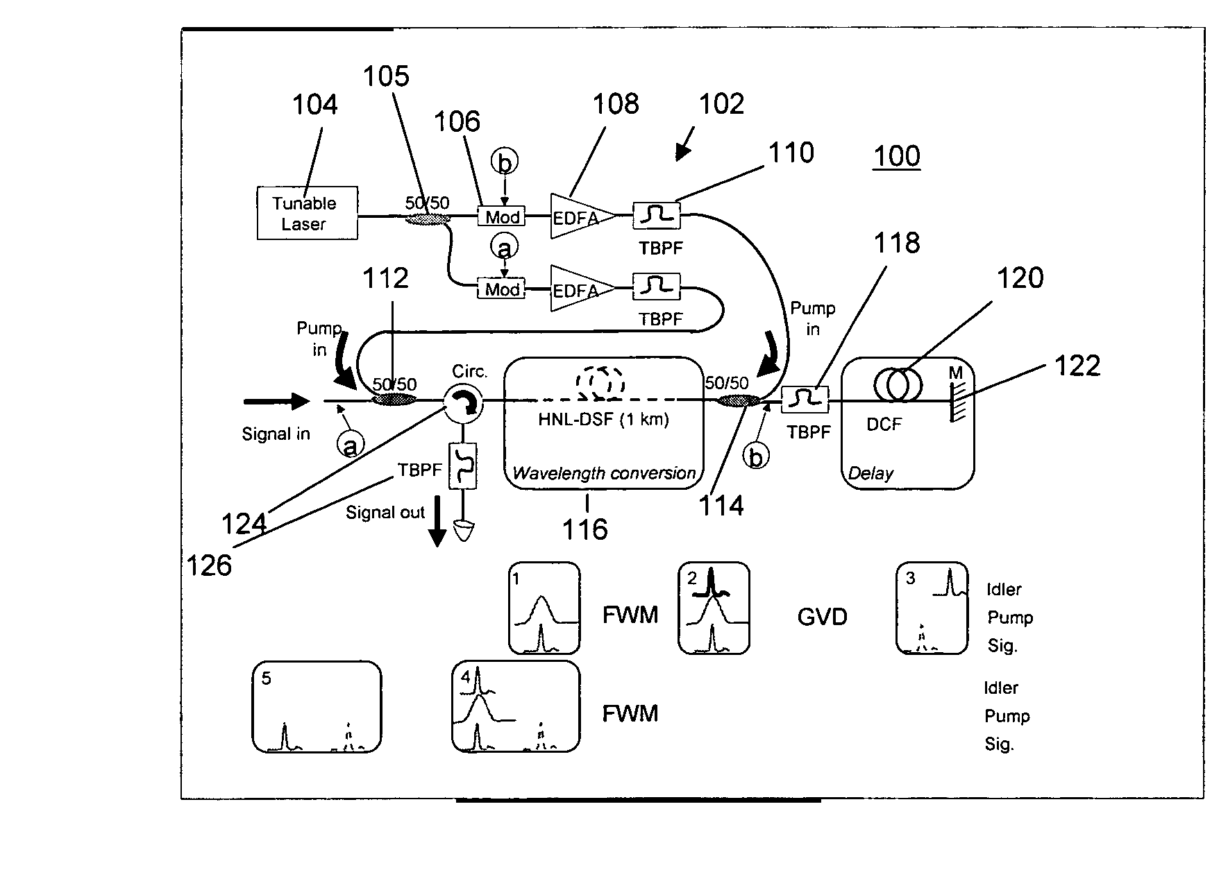
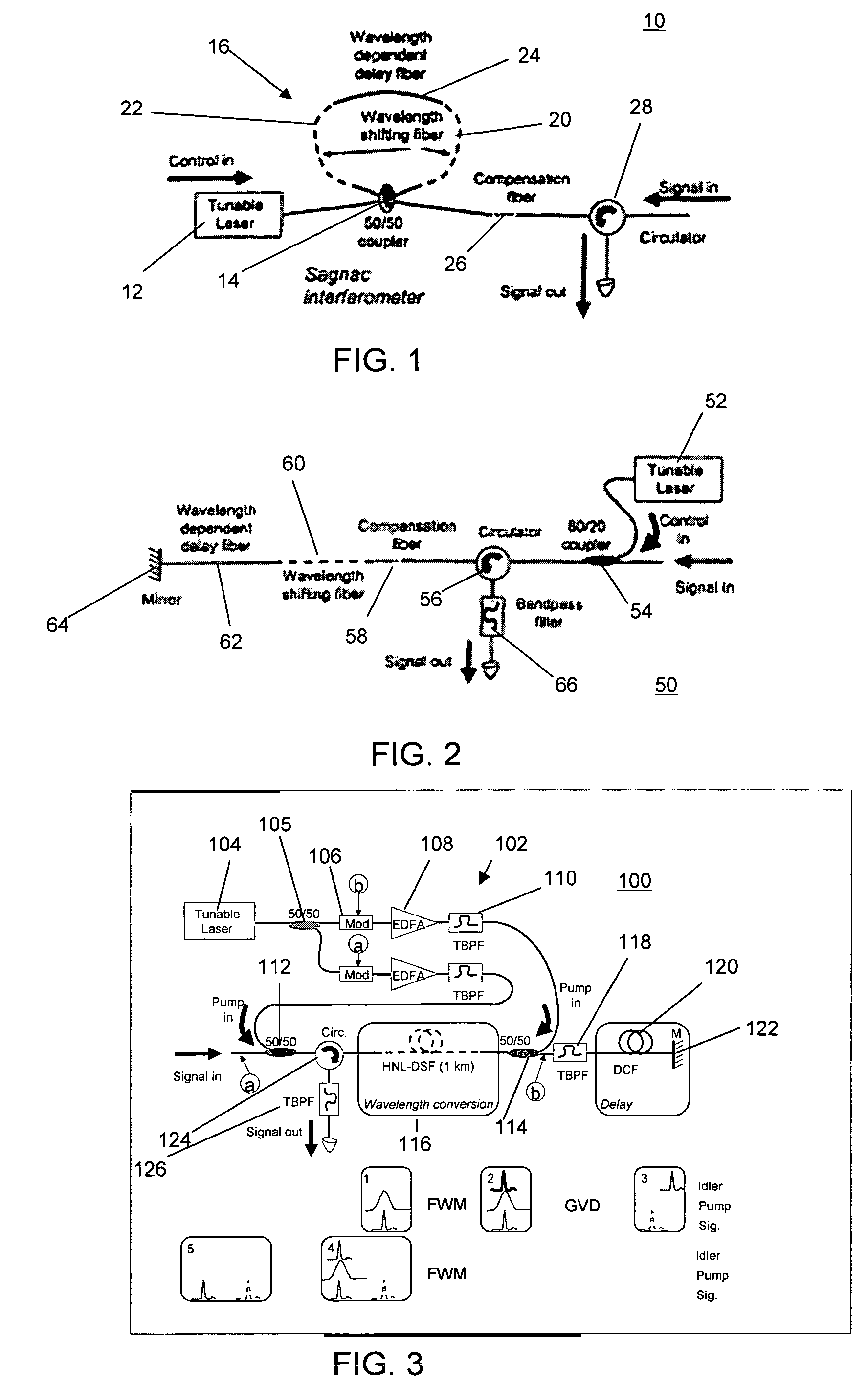
[0018]As already noted, the present invention uses one or more linear or nonlinear-optical processes such as cross-phase modulation, cross-gain modulation, four-wave mixing or parametric mixing, combined with group-velocity dispersion for generating variable pulse delays. The delay is controllable by changing the wavelength and / or power of a control laser. FIGS. 1-3 illustrate 3 possible embodiments of such a device, each of which is an “all-optical” delay generator.

[0019]With reference first to FIG. 1, an all-optical delay generator 10 is shown in which a tunable laser 12 generates a control signal that is applied along with an input signal pulse to be delayed to 50 / 50 optical coupler 14 in a Sagnac interferometer 16. The Sagnac interferometer 16 includes first and second sections 20 and 22 of wavelength shifting fiber (e.g. HNL-DSF); and a section of dispersive delay inducing fiber 24 (e.g. DCF). In this embodiment, wavelength conversion or shifting (fiber 20), wavelength dependen...


PUM

PropertyMeasurementUnit
zero-dispersion wavelengthaaaaaaaaaa
wavelengthaaaaaaaaaa

Abstract

A technique for generating variable pulse delays uses one or more nonlinear-optical processes such as cross-phase modulation, cross-gain modulation, self-phase modulation, four-wave mixing or parametric mixing, combined with group-velocity dispersion. The delay is controllable by changing the wavelength and / or power of a control laser. The delay is generated by introducing a controllable wavelength shift to a pulse of light, propagating the pulse through a material or an optical component that generates a wavelength dependent time delay, and wavelength shifting again to return the pulse to its original wavelength.

Description

CROSS REFERENCE TO RELATED APPLICATIONS[0001]This application claims the benefit, under 35 U.S.C. 119(e) of U.S. Provisional Application No. 60 / 662,391, filed Mar. 17, 2005, which is hereby incorporated by reference in its entirety. U.S. application Ser. No. 11 / 123,224, which was filed on May 6, 2005 and is commonly owned with the subject application, discloses subject matter that is related to the subject mater of this application.GOVERNMENT SPONSORSHIP STATEMENT[0002]This invention was made with Government support from the US Department of the Air Force under Contract No. F49620-03-1-0223. The Government has certain rights in the invention.BACKGROUND OF THE INVENTION[0003]1. Field of the Invention[0004]The present invention relates in general to a continuously tunable optical pulse delay generator that employs a combination of group velocity dispersion and wavelength conversion to achieve a variable delay.[0005]2. Description of the Background Art[0006]Devices that allow for tunab...

Claims


Application Information

Patent Timeline
Patent Type & Authority Patents(United States)
IPC IPC(8): G02F1/35H04B10/04H04B10/12G02F2/02H04B10/00
CPCG02F1/01G02F1/39G02F2201/20
Inventor GAETA, ALEXANDERSHARPING, JAY E.XU, CHRIS
Owner CORNELL RES FOUNDATION INC
Why Eureka
Try Eureka