
Amplifier with varying supply voltage and input attenuation based upon supply voltage

a technology of supply voltage and input attenuation, which is applied in the direction of push-pull amplifiers, phase splitters, gain control, etc., can solve the problems of radio to reset, large drop in the output voltage of the battery, and early radio shutdown that leaves considerable energy in the battery

Active Publication Date: 2009-05-26
GOOGLE TECH HLDG LLC
View PDF7 Cites 114 Cited by
  • Summary
  • Abstract
  • Description
  • Claims
  • Application Information

AI Technical Summary

Benefits of technology

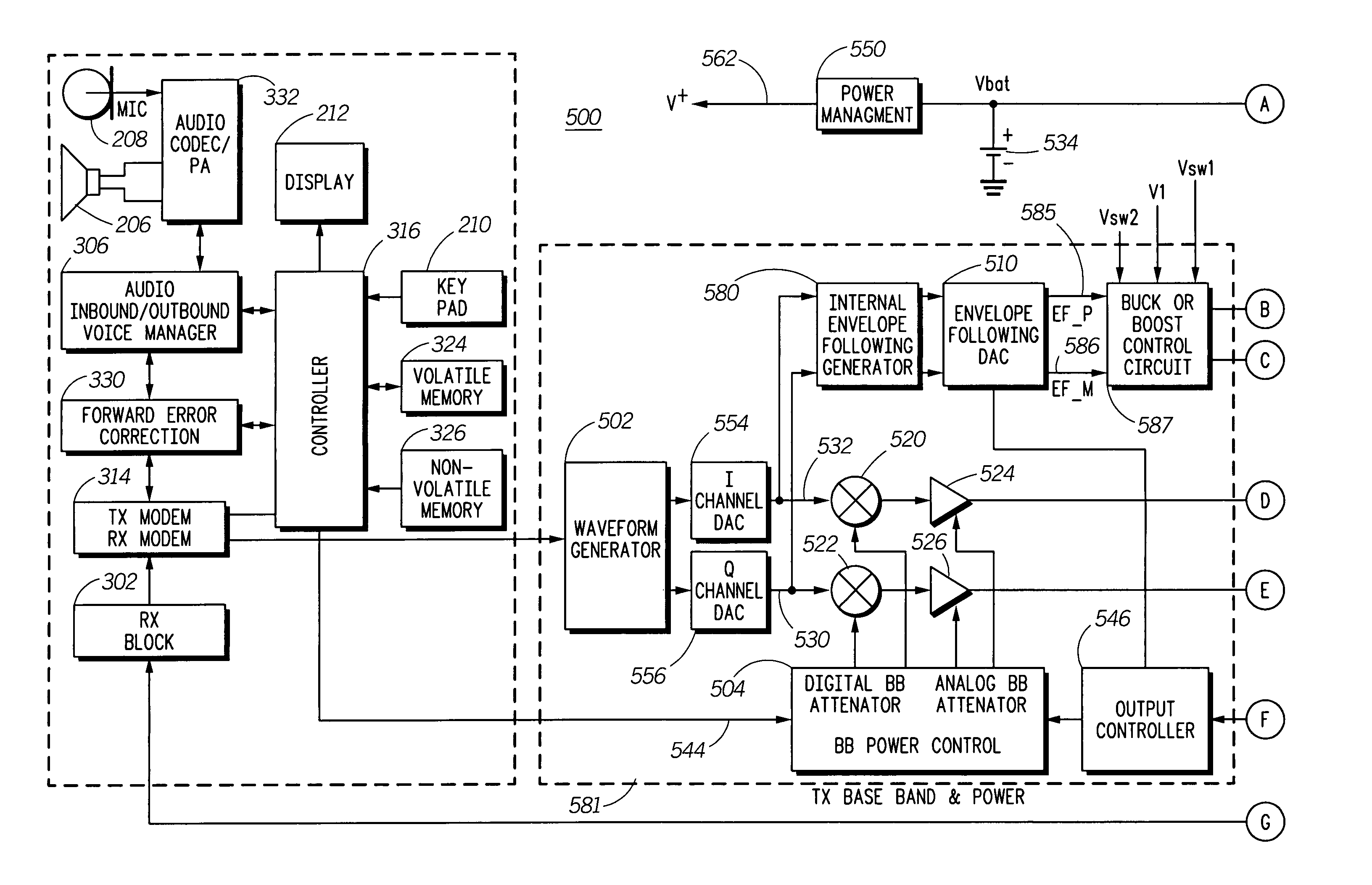
The present invention is about a radio frequency amplifier module that has a voltage monitor and an adjustable power supply. The module also has an amplifier that is supplied by the adjustable power supply and that amplifies a radio frequency signal. The output controller controls the adjustable power supply to adjust its output voltage based on the input source voltage. The technical effect of this invention is that it allows for efficient amplification of radio frequency signals with a high degree of control over the output voltage.

Problems solved by technology

The net effect of these factors is that a very large current peak by the radio frequency power amplifier causes battery monitoring circuits to determine that the battery voltage has dropped below an operating threshold, thereby triggering an early radio shutdown that leaves considerable energy in the battery.
This increased current being drawn through the internal battery resistance can cause a large drop in the output voltage of the battery.
Such high current spikes and the attendant decrease in battery output voltage can cause the radio to reset and on-going communications can be ungracefully terminated.
A further problem is that the low battery output voltage can cause the voltage regulators that supply the radio frequency circuits, such as a VCO / Synthesizer, may no longer produce a regulated output and may cause the VCO to become unlocked and cause radio frequency signal splattering that could potentially violate radio frequency transmission regulations.

Method used


Image

  • Amplifier with varying supply voltage and input attenuation based upon supply voltage
  • Amplifier with varying supply voltage and input attenuation based upon supply voltage
  • Amplifier with varying supply voltage and input attenuation based upon supply voltage

Examples


Embodiment Construction

[0015]As required, detailed embodiments of the present invention are disclosed herein; however, it is to be understood that the disclosed embodiments are merely exemplary of the invention, which can be embodied in various forms. Therefore, specific structural and functional details disclosed herein are not to be interpreted as limiting, but merely as a basis for the claims and as a representative basis for teaching one skilled in the art to variously employ the present invention in virtually any appropriately detailed structure. Further, the terms and phrases used herein are not intended to be limiting; but rather, to provide an understandable description of the invention.

[0016]The terms “a” or “an”, as used herein, are defined as one or more than one. The term plurality, as used herein, is defined as two or more than two. The term another, as used herein, is defined as at least a second or more. The terms including and / or having, as used herein, are defined as comprising (i.e., ope...


PUM


Abstract

A radio frequency amplifier module (500) has a voltage monitor (546) that monitors an input supply voltage of an input power supply (534) and an adjustable power supply (512) that accepts power from the input power supply (534) and produces an adjustable power supply output that has a controllable voltage. The radio frequency amplifier module (500) further has an amplifier (402) that is supplied by the adjustable power supply output and that amplifies a radio frequency signal. The radio frequency amplifier module (500) also has an output controller (546) that is communicatively coupled to the voltage monitor and the adjustable power supply (512). The output controller (546) controls, in response to the input source voltage, the controllable voltage of the adjustable power supply output.

Description

FIELD OF THE INVENTION[0001]The present invention generally relates to the field of radio frequency amplifiers and more particularly relates to radio frequency amplifiers that are configurable to consume reduced supply of power.BACKGROUND OF THE INVENTION[0002]Communications equipment that is powered by a battery, such as cellular telephone subscriber units, is required to operate for as long as possible from a charged battery. Some radio frequency (RF) power amplifiers (PA) used in battery powered communications equipment are configured to operate with a power supply that produces an output voltage that dynamically tracks the envelope of the RF input signal to the RF PA. This results in the power supply output voltage tracking the envelope of the amplified RF signal at the output of the RF PA. Depending on the state of the reference input signal, the output of the power supply can be higher or lower than the battery voltage. In addition to envelope tracking, the peak envelope volta...

Claims


Application Information

Patent Timeline
Patent Type & Authority Patents(United States)
IPC IPC(8): H04B1/04
CPCH03G3/3042H03G3/3047
Inventor TAN, GERONCIO O.HEFFIELD, TIMOTHY W.LEIZEROVICH, GUSTAVO D.TAN, DANILO O.
Owner GOOGLE TECH HLDG LLC
Learn More