Device and method for central on-board diagnosis for motor vehicles

a technology for motor vehicles and diagnostic devices, applied in the direction of instruments, structural/machine measurement, transportation and packaging, etc., can solve problems such as implementation and interpretation of specifications, system-wide faults cannot be detected, and limited diagnostics

Inactive Publication Date: 2009-05-26
AUDI AG +1
View PDF8 Cites 2 Cited by
  • Summary
  • Abstract
  • Description
  • Claims
  • Application Information

AI Technical Summary

Benefits of technology

[0010]Furthermore it is possible, by central execution of fault diagnosis, to omit many small storage units and obviate the necessity of computer capacity in the individual control devices, and to provide the corresponding storage including the necessary computer capacity solely in the central diagnosis device. Thus it is possible to depart from the historical development path in which control devices which are provided with self-diagnosis mechanisms were always used. Rather it is now possible to easily network control devices of different suppliers to one another and to use the status data which were made available by the control devices and which do not yet contain any diagnosis on a central basis for diagnosis.
[0011]Preferably fault diagnosis is done based on a mathematical model. Model-based fault diagnosis has the advantage that overly large databases need not be stored in individual diagnosis or control devices. Furthermore, so-called unknown fault causes can also be detected by the model-based process. They are fault causes which are not covered with the known fault codes. These fault causes can be determined by the function relationships stored in the models. For example, defective components can be inferred by finding the amount of intersection of several fault symptoms or effect relationships.

Problems solved by technology

This means that diagnosis is limited only to the control device with the respectively controlled components.
Since self-diagnosis relates only to one respective control device or its controlled components, system-wide faults cannot be detected with it.
The difficulty of system-wide fault diagnosis consists in that the control devices and controlled components generally originate from different manufacturers, and therefore different implementations and interpretations of specifications can occur.
The disadvantage here is that the function control devices are greatly burdened by the diagnosis and moreover send different types of fault codes to the higher-order diagnosis unit generally in a manner specific to the control device.

Method used


Image

  • Device and method for central on-board diagnosis for motor vehicles
  • Device and method for central on-board diagnosis for motor vehicles

Examples


Embodiment Construction

[0018]The embodiments detailed below represent preferred embodiments of this invention.

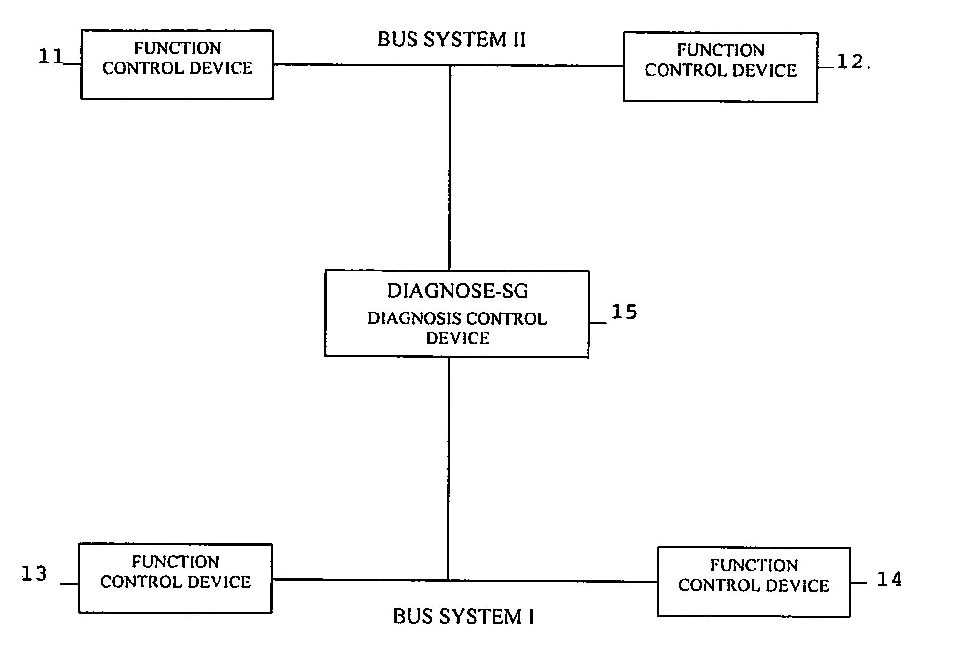
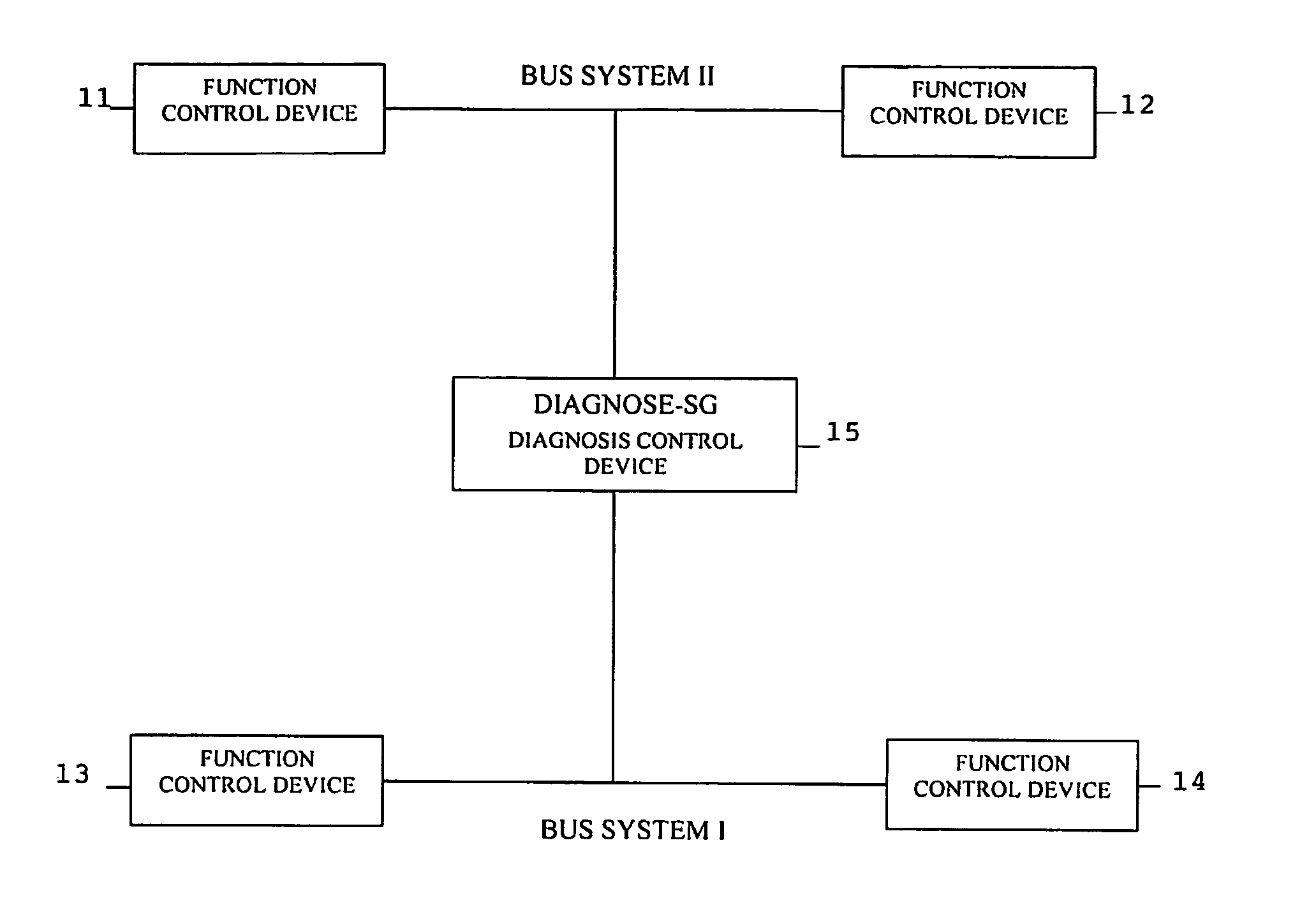
[0019]The drawings reproduce a block diagram of a simplified motor vehicle system. The motor vehicle system comprises four function control devices 11, 12, 13, and 14 and one diagnosis control device 15. The function control devices 11 and 12 are connected to the diagnosis control device 15 by way of a bus system II. The function control devices 13 and 14 are conversely connected to the diagnosis control device 15 by way of a bus system I.

[0020]The function control devices 11, 12, 13, and 14 deliver all input and output data by way of the bus systems to the diagnosis control device 15. There a complete model of the motor vehicle system for fault detection runs centrally. Thus, model-based diagnosis takes place in a control device which is intended for this purpose. Using the data obtained and the model-based diagnosis, the causative fault candidates are determined in the diagnosis control device 1...


PUM


Abstract

The aim of the invention is to improve the diagnosis of motor vehicle systems comprising a plurality of functional components in a network. To this end, the individual status data of the control units (11, 12, 13, 14) is monitored in a central diagnostic control unit (15), optionally using a mathematical model. This is advantageous in that each control unit (11, 12, 13, 14) does not have to be provided with a memory and calculation capacity for the diagnosis.

Description

[0001]This application is a § 371 application of PCT / EP2004 / 000190, which claims priority from DE 10307343.4, filed Feb. 21, 2003.BACKGROUND[0002]This invention relates to a device for on-board diagnosis for a motor vehicle system which has a plurality of control devices which are networked to one another. Furthermore this invention relates to a corresponding method for on-board diagnosis for a motor vehicle system.[0003]Fault diagnosis of control devices and of the components of a motor vehicle controlled with them is frequently carried out solely by means of self-diagnosis by the control device itself. This means that diagnosis is limited only to the control device with the respectively controlled components. If a fault is determined by self-diagnosis, a fault message is stored in the control device. Then, the fault message is retrieved in a shop using a shop tester. Since self-diagnosis relates only to one respective control device or its controlled components, system-wide faults...

Claims


Application Information

Patent Timeline
Patent Type & Authority Patents(United States)
IPC IPC(8): G01M17/00B60R16/02B60R16/03
CPCB60R16/0315
Inventor SIEBEL, ULRICHHENECKER, FRANKBREUER, ANDREAS
Owner AUDI AG
Why Eureka
Try Eureka