Startup circuit for subregulated amplifier

Active Publication Date: 2009-06-02
TEXAS INSTR INC
View PDF5 Cites 5 Cited by
  • Summary
  • Abstract
  • Description
  • Claims
  • Application Information

AI Technical Summary

Benefits of technology

[0013]A significant advantage of the described embodiments is the simplicity and reliability of the startup circuit.

Problems solved by technology

Without a startup circuit, it is possible that the second stage, because its output is dependent on parameters in the first stage, may not reach an output level high enough to power the first stage.

Method used


Image

  • Startup circuit for subregulated amplifier
  • Startup circuit for subregulated amplifier
  • Startup circuit for subregulated amplifier

Examples


Embodiment Construction

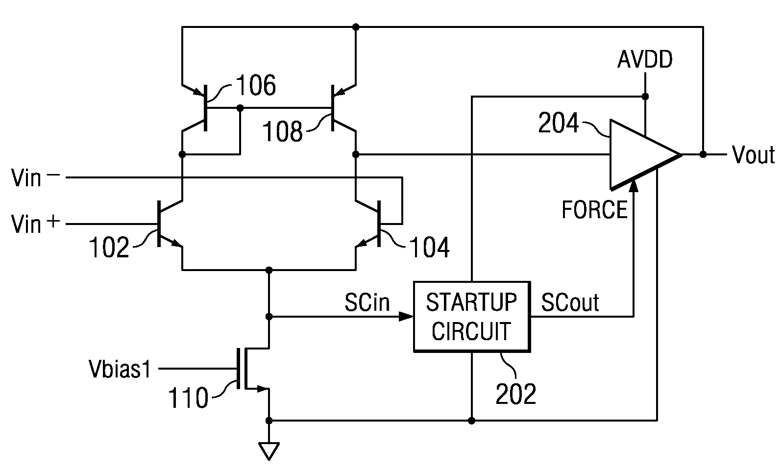
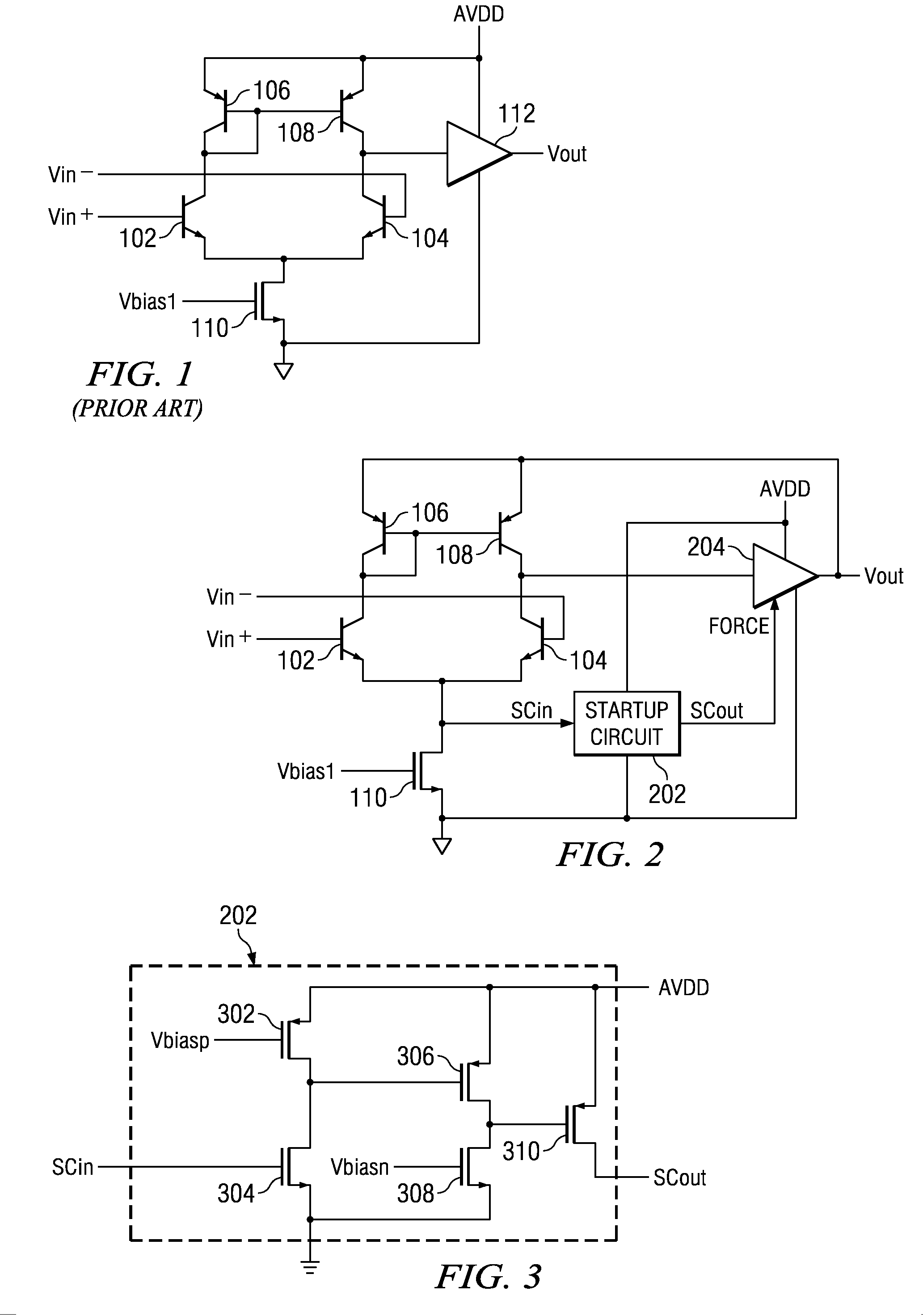
[0024]In FIG. 1 (prior art), transistors 102, 104, 106, 108 and 110 are part of a first stage differential amplifier. In a known manner, the positive input terminal Vin+ is coupled to the base of transistor 102, which has its emitter coupled to the emitter of transistor 104 and to the drain of transistor 110. The collector of transistor 102 is coupled to the collector and base of transistor 106, and to the base of transistor 108. The emitter of transistor 106 is coupled to the power supply terminal AVDD. The emitter of transistor 108 is also coupled to terminal AVDD. The negative input terminal Vin− is coupled to the base of transistor 104, which has its collector coupled to the collector of transistor 108 and to the input terminal of the second stage 112. Transistor 110 has its source coupled to ground, and its gate coupled to a bias source terminal Vbias1. Second stage 112 has a positive power supply terminal coupled to AVDD, a negative supply terminal coupled to ground, and an ou...


PUM


Abstract

A multi-stage circuit has a first stage powered by the output voltage of a next stage. A current source within the first stage provides a tail current for a differential amplifier within the first stage. When the first stage has an operating voltage high enough for proper operation, this tail current is at a nominal level; if the voltage is too low for proper operation of the first stage, the tail current is below this nominal level. A comparator, which has one input coupled to a node within this current source, a second input coupled to a threshold voltage, and an output coupled to a control node within the next stage, provides an output indicative of whether or not the tail current is substantially at its nominal level. If tail current is too low, the comparator provides a forcing signal to the control node of the next stage which causes the output of the next stage to be at a substantially nominal level regardless of the voltage at its input, thus providing a suitably high voltage for the first stage to begin normal operation. When the tail current reaches its nominal level, the comparator output changes state to one which has little or no effect on the output voltage of the second stage, and normal operation of the overall circuit begins.

Description

BACKGROUND OF THE INVENTION[0001]1. Field of the Invention[0002]This invention relates generally to startup circuits, which temporarily provide, or cause to be provided, a suitable startup operating voltage for a first subcircuit during the time immediately following application of power to the overall circuit, whereby another subcircuit coupled to and dependent on operation of the first subcircuit may become fully operational and stable prior to removal of the startup voltage; and more specifically to a startup circuit used in a bandgap voltage reference circuit in which the output node of the output stage is coupled to the preceding bandgap circuit and first stage amplifier, thereby improving power supply rejection ratio (PSRR) of the overall circuit.[0003]2. Description of the Related Art[0004]Many electronic circuits are powered by a power supply external to the circuit, thereby causing some operational parameters of the circuit to be dependent on the characteristics of the volt...

Claims


Application Information

Patent Timeline
Patent Type & Authority Patents(United States)
IPC IPC(8): H03F3/45
CPCH03F1/30H03F3/45085H03F2203/45641
Inventor OBERHUBER, RALPH
Owner TEXAS INSTR INC
Why Eureka
Try Eureka