
Link plate assembly for a chain

a technology for bicycle chains and link plates, which is applied in the direction of metal chains, chain elements, shackles, etc., can solve the problems of increasing the possibility of disengagement, prior art has the problem of strength, and the problem of disengagement cannot be overcome. , to achieve the effect of simple structure and easy assembly or disassembly of the chain

Active Publication Date: 2009-06-09
TIEN HSIN INDS
View PDF7 Cites 16 Cited by
  • Summary
  • Abstract
  • Description
  • Claims
  • Application Information

AI Technical Summary

Benefits of technology

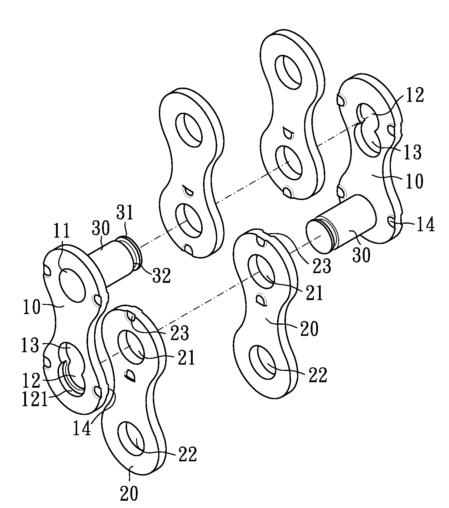
[0004]Accordingly, the primary object of the present invention is to provide a link plate assembly for a bicycle chain, wherein the structure is simple so that the rider and user can assemble or disassembly the chain easily and quickly without using special tools. Furthermore the anti-disengagement structure is provided.

Problems solved by technology

First, the prior art doesn't overcome the problem of disengagement.
This will increase the possibility of disengagement.
Second, the prior art has the problem of strength.

Method used


Image

  • Link plate assembly for a chain
  • Link plate assembly for a chain
  • Link plate assembly for a chain

Examples


Embodiment Construction

[0012]In order that those skilled in the art can further understand the present invention, a description will be provided in the following in details. However, these descriptions and the appended drawings are only used to cause those skilled in the art to understand the objects, features, and characteristics of the present invention, but not to be used to confine the scope and spirit of the present invention defined in the appended claims.

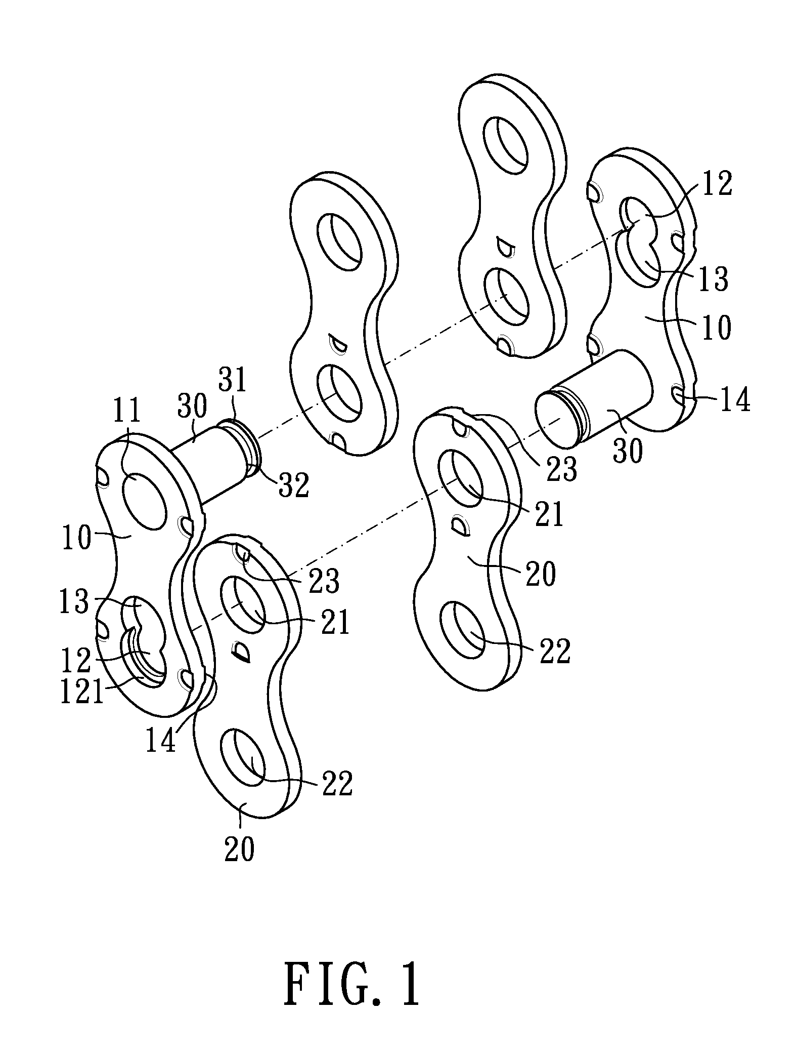
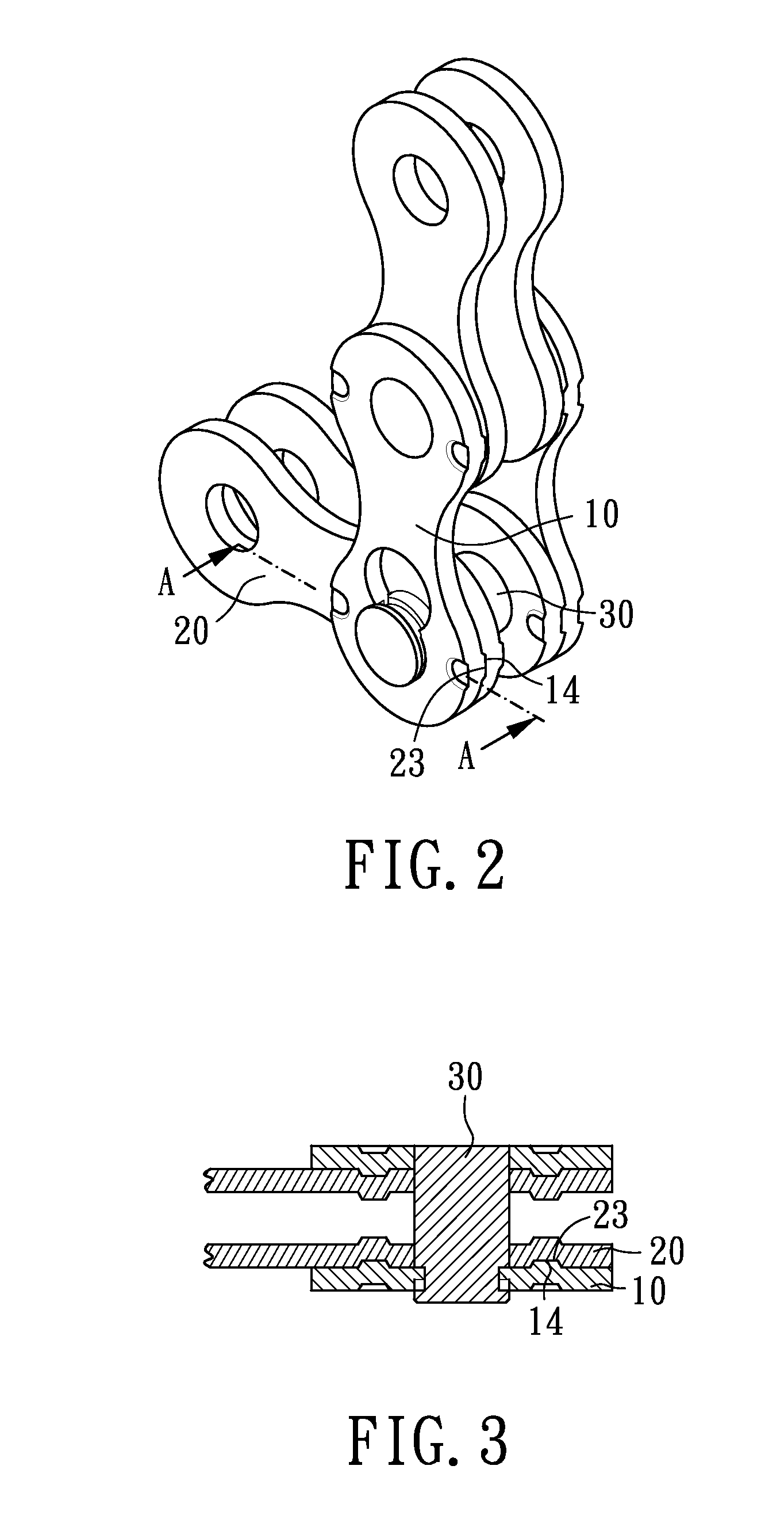
[0013]With reference to FIGS. 1 to 5, a link plate assembly according to the present invention is illustrated. The link plate assembly includes two first plates 10, four second plates 20, and two pins 30.

[0014]Referring to FIG. 1, each of the first plates 10 includes a first aperture 11, a second aperture 12 and a receiving aperture 13. The receiving aperture 13 connects to second aperture 12 and the diameter of the receiving aperture 13 is greater than the diameter of the second aperture 12. Four convex portions 14 facing the second plate 22 are f...


PUM

PropertyMeasurementUnit
Timeaaaaaaaaaa
Timeaaaaaaaaaa
Angleaaaaaaaaaa

Abstract

A link plate assembly includes two first plate, two second plate, and two pins. The first plate includes a first aperture, a second aperture and a receiving aperture. Four convex portions facing the second plate are formed on the first plate. The second plate includes a first aperture and a second aperture. Two concave portions facing the first plate are formed on the second plate. One end of each pin is secured to the first aperture of the first plate. The other end of each pin includes a head portion and a groove portion. The head portion passes through the first aperture of the second plates and the receiving aperture of the other first plate. The groove portion passes through the second aperture of the first plate. The convex portions of the first plates contact with a non-concave part of the second plates when assembling. The convex portions coincide with the concave portions to disassemble the link plate assembly as the second plate is rotated relative to the first plate in a predetermined angle.

Description

FIELD OF THE INVENTION[0001]The present invention relates to a link plate assembly for a bicycle chain, and particularly to a link plate assembly which minimizes the possibility of accidental disengagement and is assembled and disassembled easily.BACKGROUND OF THE INVENTION[0002]Referring to U.S. Pat. No. 5,362,282, “master chain link” is disclosed, in that a reusable master chain link for a derailleur chain is provided, which includes first and second parallel pins extending between first and second parallel plates. The first pin includes first and second heads at opposite ends thereof and the second pin also includes first and second heads at opposite ends thereof. The first and second plates have respective first and second apertures formed therein. The first and second apertures have respective narrow circular portions narrower than the respective first heads of the first and second pins. The narrow circular portions further include respective countersinks formed therein for rec...

Claims


Application Information

Patent Timeline
IPC IPC(8): F16G13/06F16G15/06
CPCF16G13/06
Inventor CHIN, CHIH-CHUNG
Owner TIEN HSIN INDS
Learn More