Circuit breaker cradle with an interlock system and a method of using the same

a circuit breaker and interlocking technology, applied in the field of electrical switchgear, can solve the problem that the circuit breaker is not adapted for mounting in the cell

Active Publication Date: 2009-06-09
ABB (SCHWEIZ) AG
View PDF3 Cites 34 Cited by
  • Summary
  • Abstract
  • Description
  • Claims
  • Application Information

AI Technical Summary

Benefits of technology

[0007]In accordance with the present invention, a cradle is provided for adapting a circuit breaker for mounting in a cell of a switchgear cabinet having a bus bar system. The cradle includes a frame for holding the circuit breaker. The frame includes a bottom structure and a pair of opposing side structures that help define a holding space for receiving the circuit breaker. A racking apparatus is mounted to the frame. The racking apparatus is operable to move the cradle between a first position, wherein the cradle is not electrically connected to the bus bar system, and a second position, wherein the cradle is electrically connected to the bus bar system. A locking apparatus is mounted to the frame. The locking apparatus has first and second operating states. When the locking apparatus is in the first operating state, the locking apparatus prevents the circuit breaker from being disposed in the holding space of the frame and allows the racking apparatus to move the cradle between the first and second positions. When the locking apparatus is in the second operating state, the locking apparatus allows the circuit breaker to be disposed in the holding space of the frame and prevents the racking apparatus from moving the cradle between the first and second positions.

Problems solved by technology

The circuit breaker is not adapted for mounting in the cell.

Method used


Image

  • Circuit breaker cradle with an interlock system and a method of using the same
  • Circuit breaker cradle with an interlock system and a method of using the same
  • Circuit breaker cradle with an interlock system and a method of using the same

Examples


Embodiment Construction

[0017]It should be noted that in the detailed description that follows, identical components have the same reference numerals, regardless of whether they are shown in different embodiments of the present invention. It should also be noted that in order to clearly and concisely disclose the present invention, the drawings may not necessarily be to scale and certain features of the invention may be shown in somewhat schematic form.

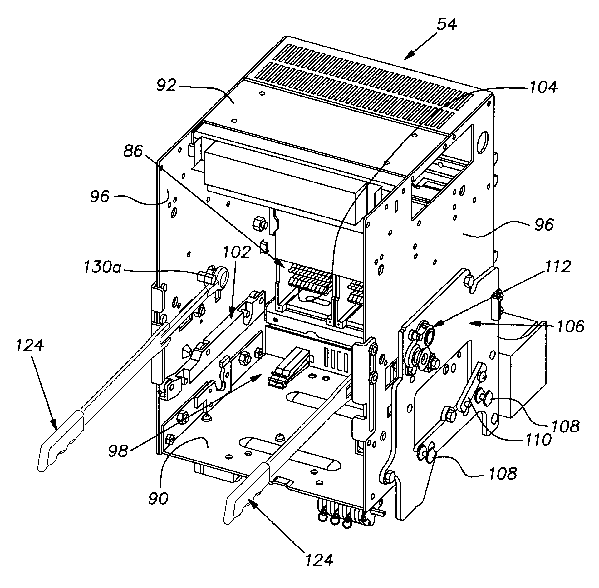
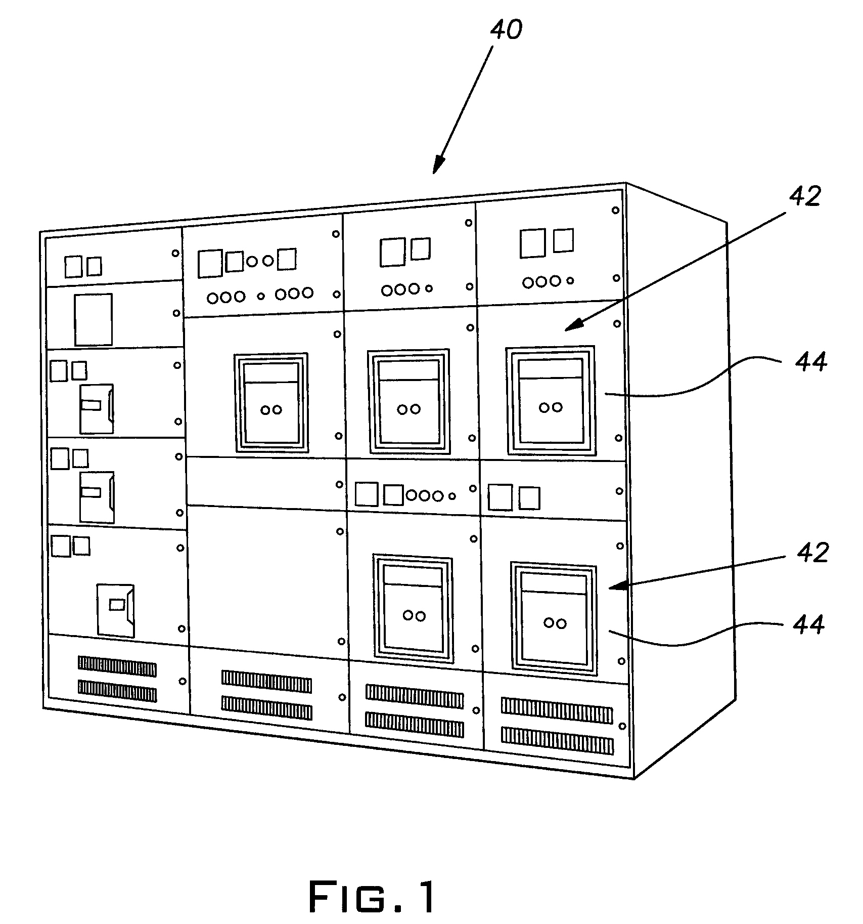
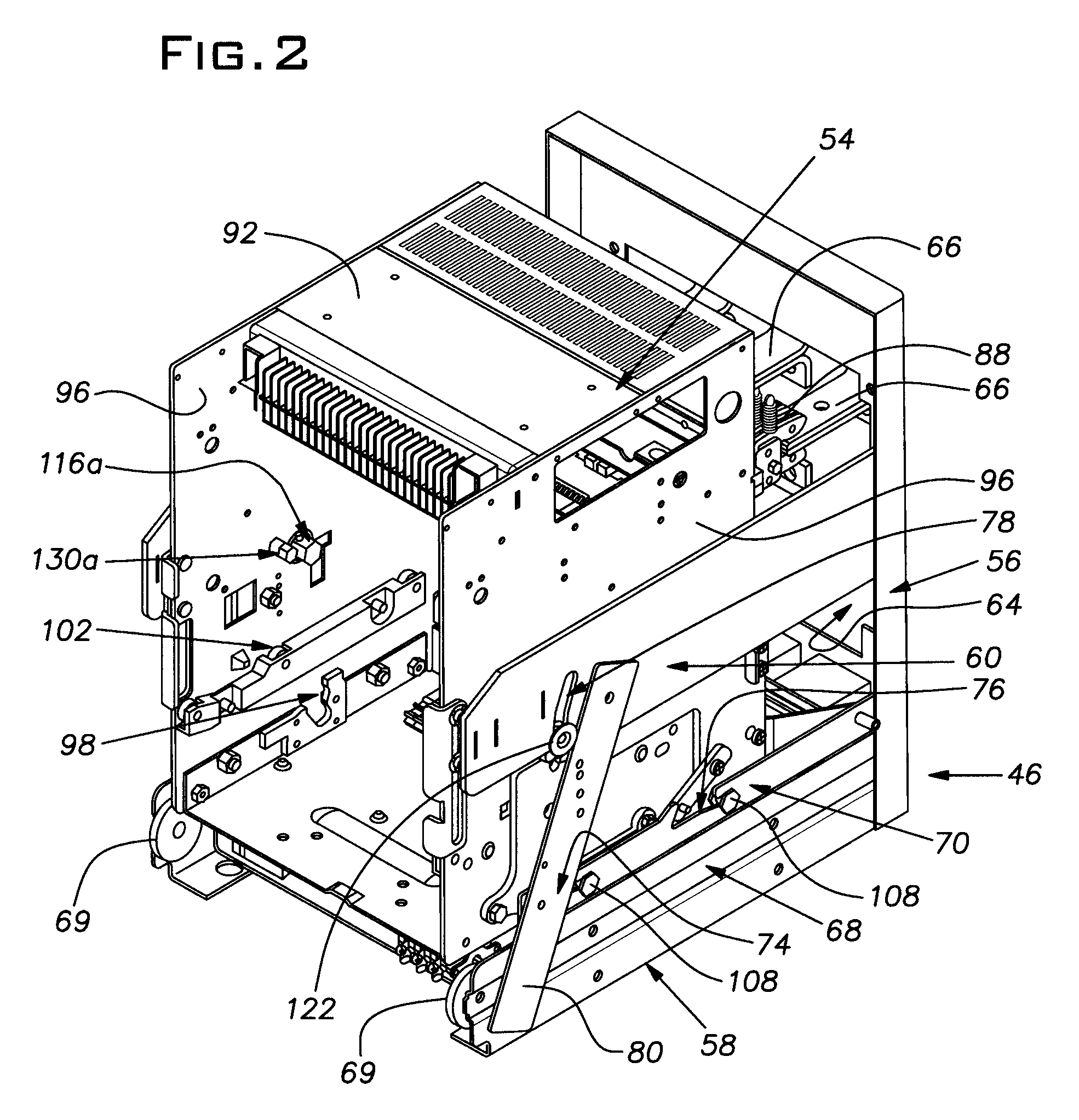
[0018]Referring now to FIG. 1 there is shown a switchgear cabinet 40 having a plurality of cells 42 for holding circuit breakers. Each cell 42 is closed by a door 44 having a cut-out through which the front of a circuit breaker may be accessed. A substructure 46 (shown in FIGS. 2-3) is mounted in each cell 42. Each substructure 46 was originally designed and constructed to hold a first circuit breaker 48 (shown in FIG. 4). For purposes of better describing the invention, it should be noted that it is desired to replace each first circuit breaker 48 with a se...


PUM


Abstract

A cradle and a method for adapting a circuit breaker for mounting in a switchgear cabinet having a bus bar system. The cradle includes a frame to which a racking apparatus and a locking apparatus are mounted. The racking apparatus is operable to move the cradle into and out of electrical connection with the bus bar system. The locking apparatus has a first operating state, wherein the locking apparatus prevents the circuit breaker from being disposed in the frame and allows the racking apparatus to operate, and a second operating state, wherein the locking apparatus allows the circuit breaker to be disposed in the frame and prevents the racking apparatus from operating.

Description

CROSS-REFERENCE TO RELATED APPLICATION[0001]This application claims the benefit of U.S. provisional patent application No. 60 / 946,320 filed on Jun. 26, 2007, which is hereby incorporated by reference in its entirety.BACKGROUND OF THE INVENTION[0002]The present invention relates to electrical switchgear, and more particularly, to an adapter system and method for retrofitting existing switchgear with new, removable circuit breakers.[0003]Many types of low- and medium-voltage switchgear systems use circuit breakers that can be withdrawn for maintenance. Typically, such a circuit breaker is moved into and out of a switchgear cell by a racking mechanism having arms disposed on opposing sides of the circuit breakers and which are only movable simultaneously. Further, such a circuit breaker typically has an interlock that prevents the circuit breaker from being moved into or out of connection with the bus bar in the switchgear cell when the circuit breaker is closed.[0004]As a switchgear i...

Claims


Application Information

Patent Timeline
Patent Type & Authority Patents(United States)
IPC IPC(8): H01H9/20H01H9/24
CPCH02B11/127
Inventor WEBB, JOHN C.JONES, MURRAY K.
Owner ABB (SCHWEIZ) AG
Why Eureka
Try Eureka