
Filter with multiple shunt zeros

a filter and zero technology, applied in the field of electric filters, can solve the problems of reducing the ability of filters to attenuate/reject unwanted frequencies, increasing insertion loss and bandpass frequency ripple, and high ripple, and achieves high rejection/attenuation. , the effect of increasing the rippl

Inactive Publication Date: 2009-06-09
CTS CORP ELKHART
View PDF25 Cites 9 Cited by
  • Summary
  • Abstract
  • Description
  • Claims
  • Application Information

AI Technical Summary

Benefits of technology

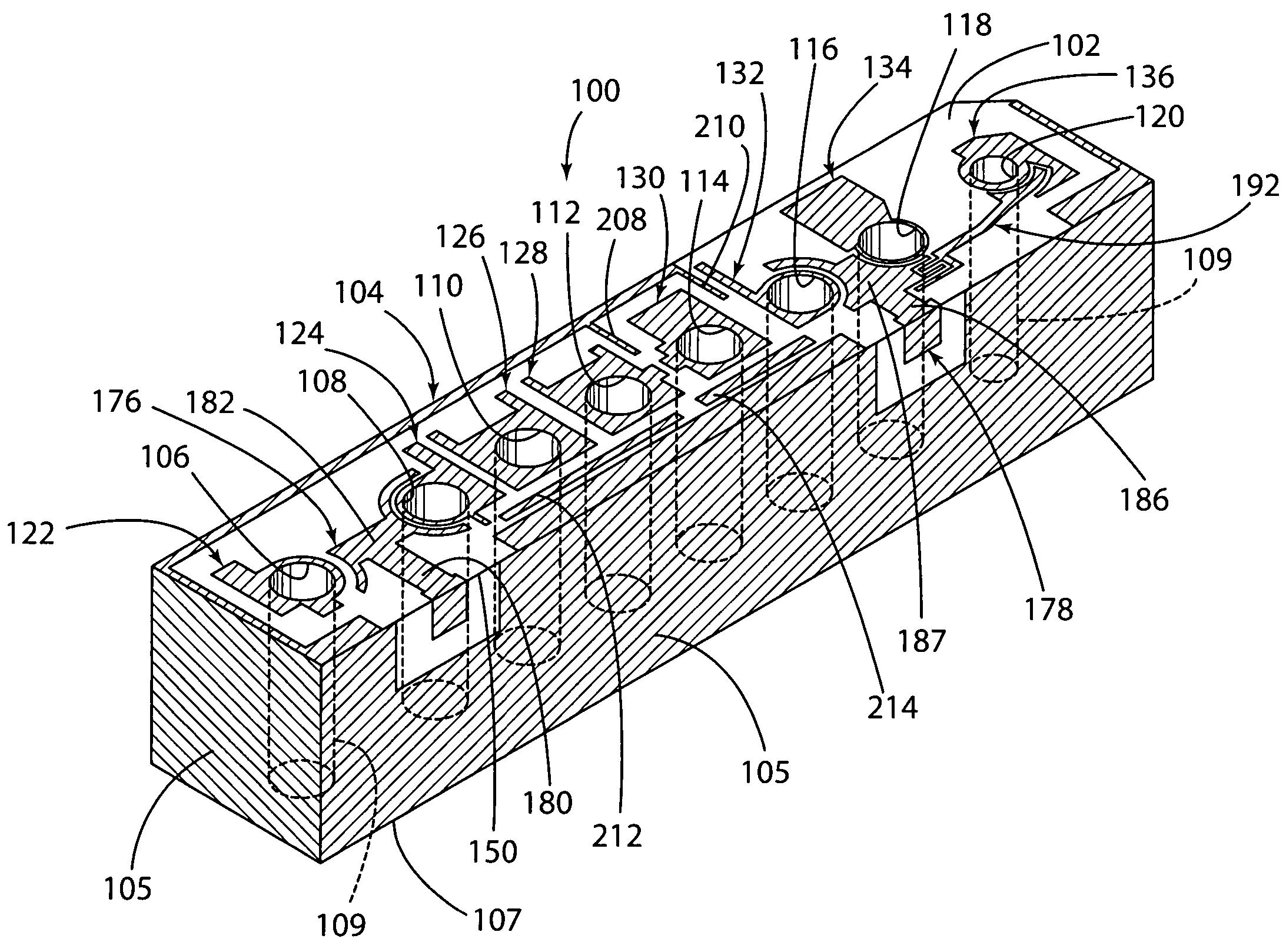
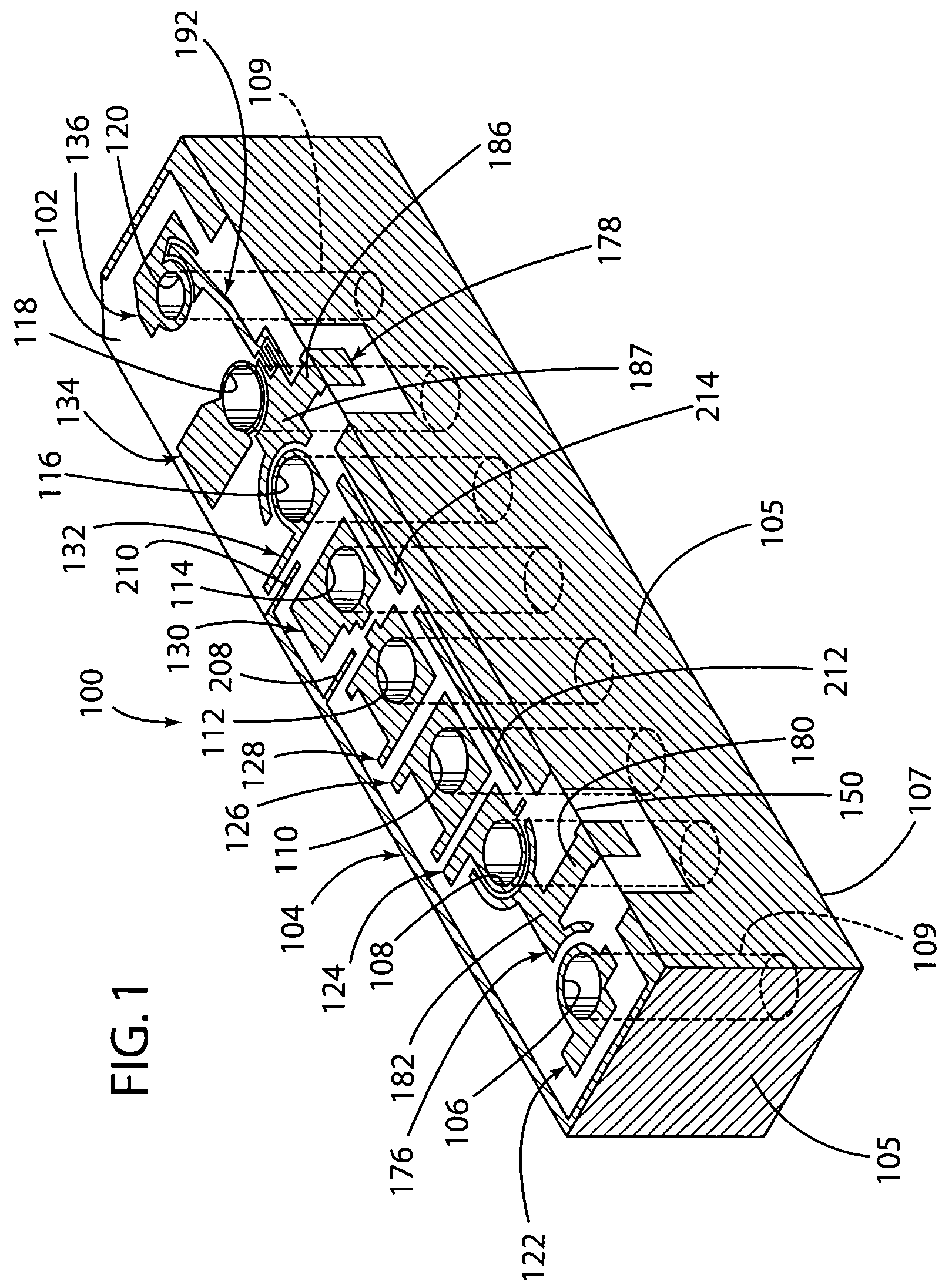
The present invention is a filter that has a block with conductive surfaces and through-holes that are also covered with conductive material. The filter also has plates that surround the through-holes and define apertures in the top surface. The filter has first and second shunt zeros that are defined by the plates and resonator through-holes. The filter also has an input / output pad that is capacitively or inductively coupled to the through-holes. The combination of the filter with multiple shunt zeros and the input / output pad provides high rejection / attenuation without any increase in ripple.

Problems solved by technology

A wider bandwidth, however, reduces a filter's ability to attenuate / reject unwanted frequencies, i.e., frequencies which are known in the art as rejection frequencies.
One disadvantage, however, which has been associated with the use of a single shunt zero is the increase in insertion loss and bandpass frequency ripple (e.g., the delta between the minimum and maximum points of a bandpass's insertion loss) as the rejection / attenuation moves closer and closer to the start and / or stop frequencies of the bandpass.
This disadvantage is of particular significance and consequence in repeater, micro cell and pico cell filter applications where high rejection and low bandpass ripple are two of the critical performance parameters.
However, when filters are set up in series, high ripple and low rejection become a problem since lesser rejection causes distortion and excess ripple reduces the effective transmission distance of the repeater.

Method used


Image

  • Filter with multiple shunt zeros
  • Filter with multiple shunt zeros
  • Filter with multiple shunt zeros

Examples


Embodiment Construction

[0022]While this invention is susceptible to embodiments in many different forms, this specification and the accompanying drawings disclose only one preferred embodiment as an example of the present invention. The invention is not intended, however, to be limited to the embodiment so described.

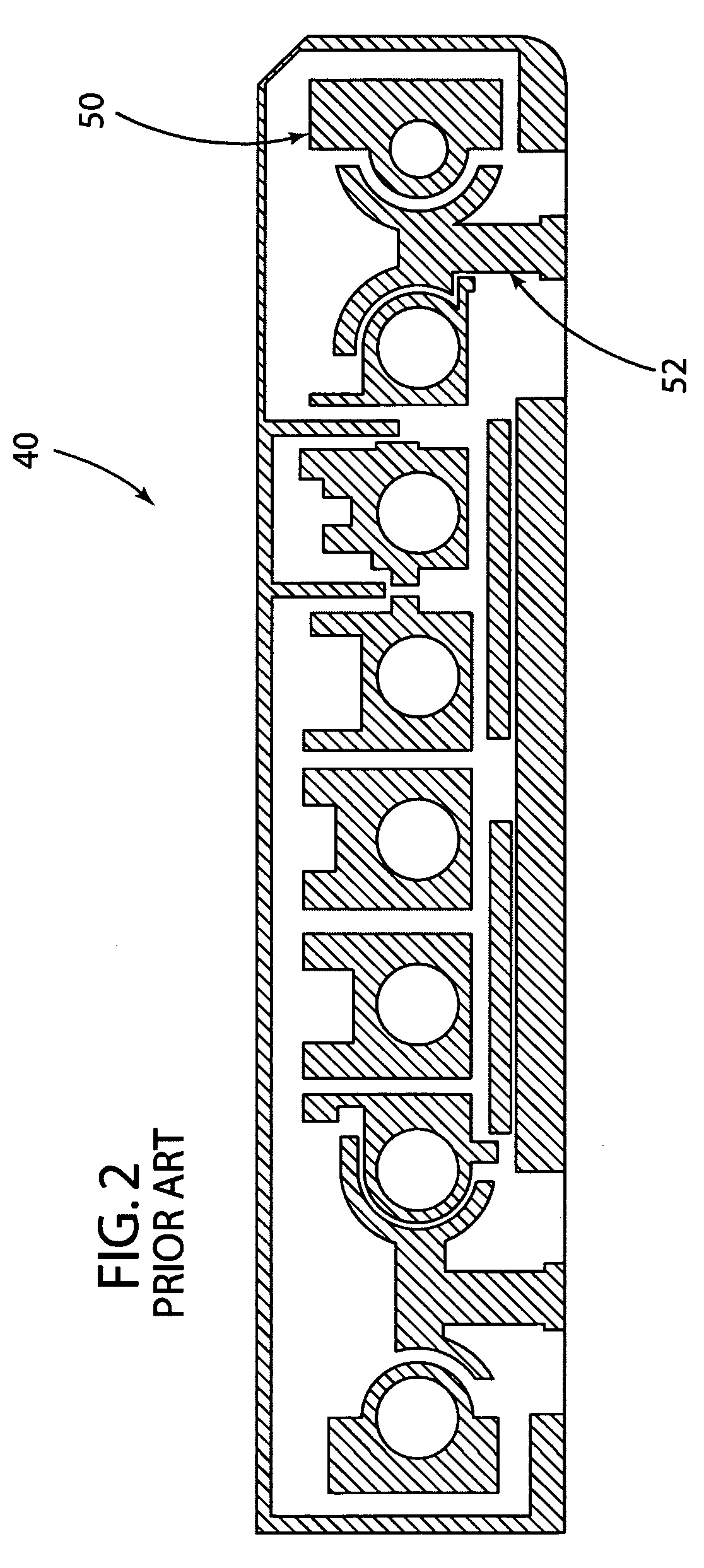
[0023]FIG. 2 depicts the top surface of a standard ceramic monoblock filter 40 incorporating a single shunt zero 50 of the same general type disclosed in, for example, U.S. Pat. No. 6,559,735 to Hoang and Vangala; and U.S. Pat. No. 5,502,422 to Newell et al. Shunt zero 50 is coupled directly to an input / output pad 52.

[0024]FIGS. 1 and 3 depict a simplex filter 100 constructed in accordance with the principles of the present invention. As is known in the art, a simplex filter is a filter with a single bandpass where one of the I / O (input / output) pads on the block provides the signal input and the other I / O pad provides the signal output. A bandpass filter's function is determined by the applica...


PUM


Abstract

A filter including at least two resonator through-holes defining apertures in the top surface surrounded by respective plates which in combination with the through-holes associated therewith define primary and secondary shunt zeros adapted to provide low ripple and high rejection adjacent the bandpass. In the embodiment shown, the through-hole of the primary shunt zero is directly capacitively or inductively coupled to an input / output pad, while the through-hole of the secondary shunt zero is indirectly capacitively or inductively coupled to the input / output pad via a coupling bar extending between the input / output pad and the secondary shunt zero. In another embodiment, the secondary shunt zero may be capacitively or inductively coupled directly to the input / output pad. In still a further embodiment, more than two of the resonator through-holes in combination with respective plates associated therewith define additional shunt zeros capacitively or inductively coupled directly or indirectly to the input / output pad.

Description

CROSS-REFERENCE TO RELATED APPLICATION[0001]This application claims the benefit of the filing date of U.S. Provisional Application Ser. No. 60 / 684,140, filed on May 24, 2005, which is explicitly incorporated herein by reference as are all references cited therein.TECHNICAL FIELD[0002]This invention relates to electrical filters and, in particular, to a dielectric filter with multiple shunt zeros.BACKGROUND OF THE INVENTION[0003]As is well known in the art, filters provide for the attenuation / rejection of signals with frequencies outside of a particular frequency range and little rejection / attenuation to signals with frequencies within a particular range of interest. These filters most typically take the form of blocks of ceramic material having one of more resonators / poles formed therein such as, for example, the ceramic filters disclosed in U.S. Pat. No. 4,431,977 to Sokola et al. and U.S. Pat. No. 4,692,726 to Green et al. A ceramic filter may be constructed to define either a low...

Claims


Application Information

Patent Timeline
Patent Type & Authority Patents(United States)
IPC IPC(8): H01P1/205
CPCH01P1/2056H01P1/205
Inventor MORGA, JUSTIN RUSSELL
Owner CTS CORP ELKHART
Learn More