Battery system comprising a hybrid battery and an npc inverter which is connected at the input end to the battery, and method for operating an npc inverter which is connected at the input end to a hybrid battery

一种混合电池组、电池组的技术,应用在电池/电池的牵引、交流功率输入变换为直流功率输出、电池电路装置等方向,能够解决储能电池寿命影响等问题,达到高效率的效果

Active Publication Date: 2017-08-18
ROBERT BOSCH GMBH
View PDF7 Cites 3 Cited by
  • Summary
  • Abstract
  • Description
  • Claims
  • Application Information

AI Technical Summary

Problems solved by technology

This adversely affects the lifetime of the energy storage battery

Method used


Image

  • Battery system comprising a hybrid battery and an npc inverter which is connected at the input end to the battery, and method for operating an npc inverter which is connected at the input end to a hybrid battery
  • Battery system comprising a hybrid battery and an npc inverter which is connected at the input end to the battery, and method for operating an npc inverter which is connected at the input end to a hybrid battery
  • Battery system comprising a hybrid battery and an npc inverter which is connected at the input end to the battery, and method for operating an npc inverter which is connected at the input end to a hybrid battery

Examples


no. 2 approach

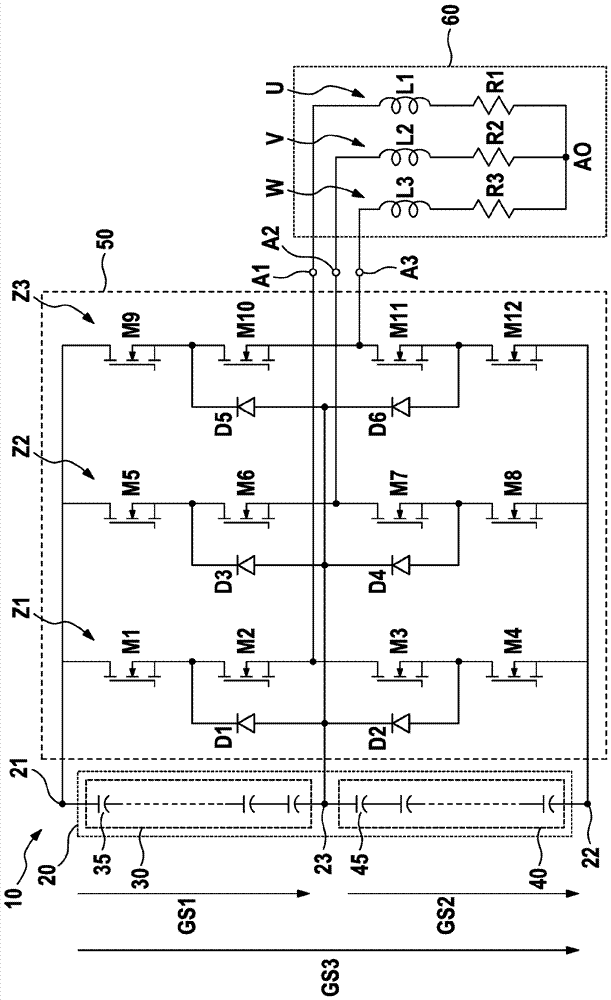
[0063] According to the second embodiment of the invention, an IGBT T1, . . . , T12 is assigned to each n-channel MOSFETM1, . . . , M12, respectively. Here, each IGBT T1 , . . . , T12 is connected in parallel with the n-channel MOSFET M1 , . . . , M12 assigned to it. To this end, each IGBT T1,..., T12 comprises an emitter terminal and a collector terminal, wherein each IGBT T1,..., T12 is connected via its emitter terminal to the source terminal of the assigned n-channel MOSFET M1,..., M12 are connected directly and via their collector terminals to the drain terminals of the assigned n-channel MOSFETs M1, . . . , M12. The emitter terminal of each IGBT T1,...,T12 is also directly connected to the anode of the free-wheeling diode assigned to that IGBT, and the collector terminal of each IGBT TT1,...,T12 is directly connected to the cathode of the free-wheeling diode assigned to that IGBT ground connection. To simplify Figure 5 , the freewheeling diodes assigned to the twelve...


PUM


Abstract

The present invention relates to a battery system which has a hybrid battery which comprises a first energy storage source having a plurality of first energy storage cells and comprises a second energy storage source which is connected in series with the first energy storage source and has a plurality of second energy storage cells which are different from the first energy storage cells. Furthermore, the battery system has an inverter which is connected at the input end to the battery and is designed to convert a DC voltage which is supplied to the input end into an, in particular polyphase, AC voltage which is produced at the output end. The battery system also has a control unit which is designed to operate the inverter in a first functional mode or in a second functional mode or in a third functional mode by controlling a plurality of semiconductor switches of the inverter. In the first functional mode, the inverter converts a DC voltage which is provided by the first energy storage source and is supplied to the input end into the AC voltage which is produced at the output end. In the second functional mode, the inverter converts a DC voltage which is provided by the second energy storage source and is supplied to the input end into the AC voltage which is produced at the output end. In the third functional mode, the inverter converts a DC voltage which is provided by a series circuit comprising the first energy storage source and the second energy storage source and is supplied at the input end into the AC voltage which is produced at the output end.

Description

technical field [0001] The invention relates to a battery system with a hybrid battery and an inverter which is connected to the battery on the input side. The invention also relates to a method for operating an inverter connected on the input side to a hybrid battery pack. Furthermore, the invention relates to a vehicle having such a battery system and an electric motor connected on the output side to an inverter. Background technique [0002] NPC inverters (NPC inverters) with at least three voltage levels (voltage levels (Spannungspegel)), also known as neutral inverters with at least three voltage levels, are known from the prior art. Point-clamped diode multilevel inverter (Neutral-Point-Clamped-Diode-Multilevel-Inverter, NPC). Such NPC inverters with a number n of voltage levels are supplied with electrical energy via n-1 voltage sources or storage energy sources. The DC voltage generated by the voltage source or energy store is supplied to the NPC inverter on the i...

Claims


Application Information

Patent Timeline
Patent Type & Authority Applications(China)
IPC IPC(8): H02M7/487
CPCH02M7/487H02J7/345H02M1/088B60L50/51B60L50/64H02J7/0014Y02T10/70B60L15/007B60L2210/42B60L2240/52H02M7/53871H02P27/06
Inventor V.德格W.扎哈里C.沃尔
Owner ROBERT BOSCH GMBH
Why Eureka
Try Eureka