
Refrigerator and display device guiding apparatus of the same

a technology of display device and refrigerator door, which is applied in the direction of lighting and heating apparatus, domestic cooling apparatus, furniture parts, etc., can solve the problems of affecting the thickness of the door in relation to the radius of the curved portion, and the user's inability to see the image on the display device screen, etc., to reduce the insulation loss of the refrigerator door, improve the straight advancement, and reduce the depth of the display device receiving portion.

Inactive Publication Date: 2009-06-16
LG ELECTRONICS INC
View PDF14 Cites 35 Cited by
  • Summary
  • Abstract
  • Description
  • Claims
  • Application Information

AI Technical Summary

Benefits of technology

The present invention provides a refrigerator and display device guiding apparatus that solves various problems of existing refrigerators and display devices. The technical effects of the invention include reducing the depth of the display device receiving portion and reducing insulation loss of the refrigerator door, solving the view angle problem of the display device in the left and right directions, preventing interference with outer wall of the refrigerator and other components such as a door handle, and improving straight advancement of the display device to allow for convenient use by the user.

Problems solved by technology

However, although the flat display device can solve the insulation thickness problem of the door, it may provide a dead angle at which the screen of the display device is hidden by, for example, a door handle and thus the user cannot see the image on the screen of the display device.
Furthermore, since the flat display such as the LCD and PDP has an inherent view angle problem, the user can clearly watch the image on the screen within a predetermined angle range.
However, since a display device receiving portion must be curved in response to the pivotal angle of the display device, a thickness of the door is affected in relation to the size of the radius of the curved portion.
When the depth of the receiving portion is increased, the insulating efficiency of the refrigerator is deteriorated.
Furthermore, since the pivotal hinges are formed on left and right sides of the display device, the pivot direction of the display device is limited in a vertical direction.
Therefore, the view angle problem in the left and right directions and the dead angle problem caused by the door handle cannot be still solved.

Method used


Image

  • Refrigerator and display device guiding apparatus of the same
  • Refrigerator and display device guiding apparatus of the same
  • Refrigerator and display device guiding apparatus of the same

Examples


first embodiment

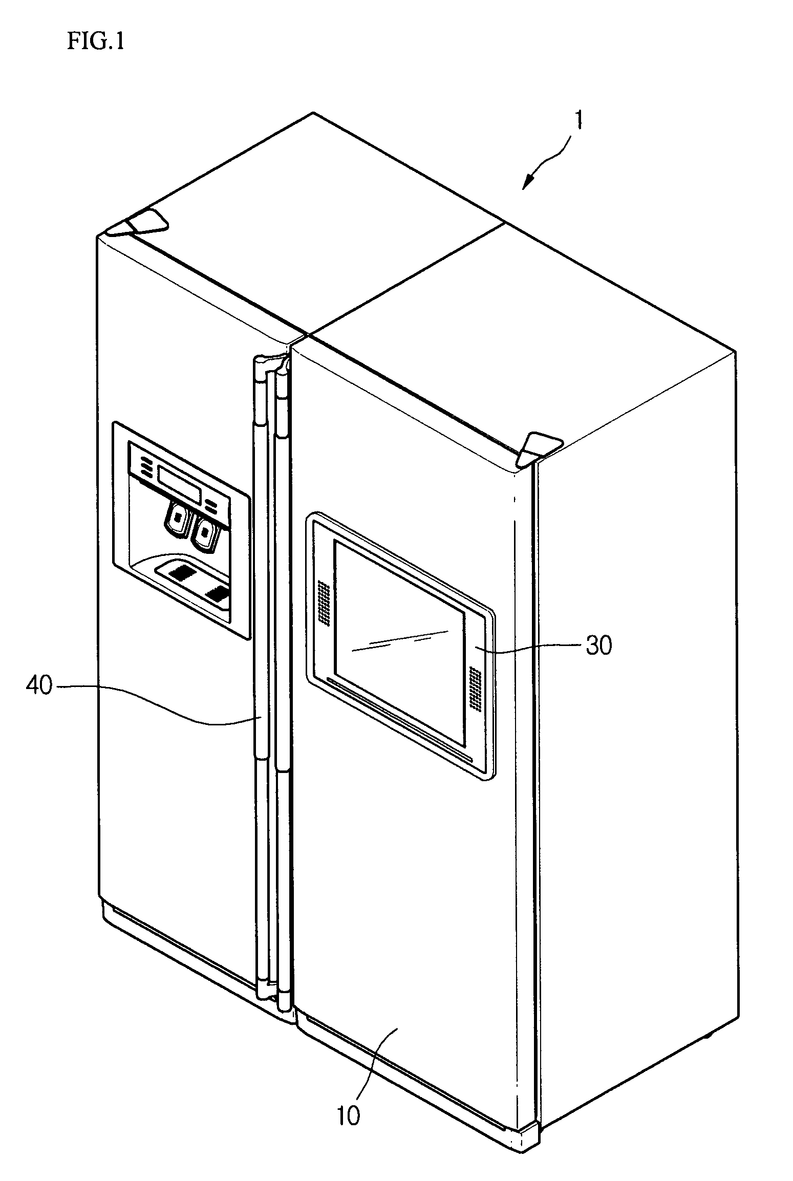
[0043]FIG. 1 shows a perspective view of a refrigerator according to an embodiment of the present invention.

[0044]Referring to FIG. 1, a refrigerator 1 includes a door movable for sealing or opening an inner space of the refrigerator 1, a display device 30 formed on a front surface of the door 10, and a door handle 40 used for opening and closing the door. While show in FIG. 1 is a side-by-side refrigerator, the present invention is also applicable to top-freezer and bottom-freezer type refrigerators as well as to any other type of home appliance including a display.

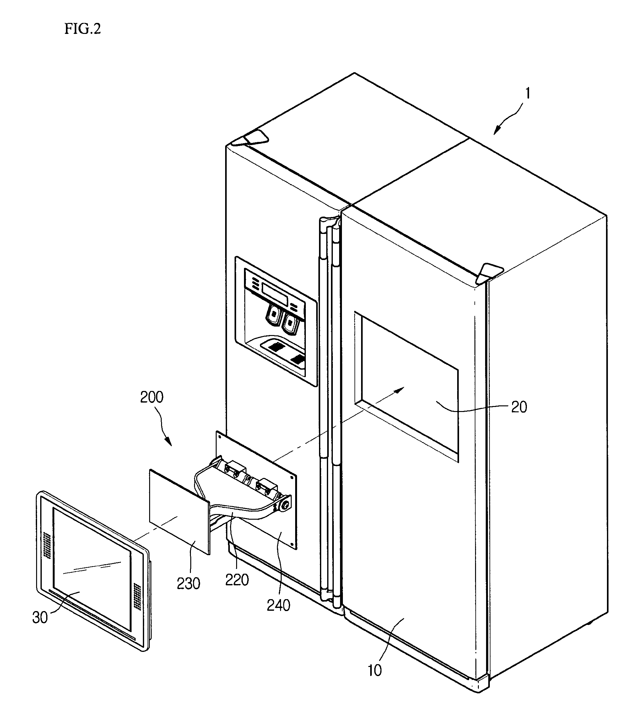
[0045]The user can more conveniently use the refrigerator using images displayed on the display device 30. The display device 30 may be used in a state where it is embedded in the door 10 or it is advanced frontward.

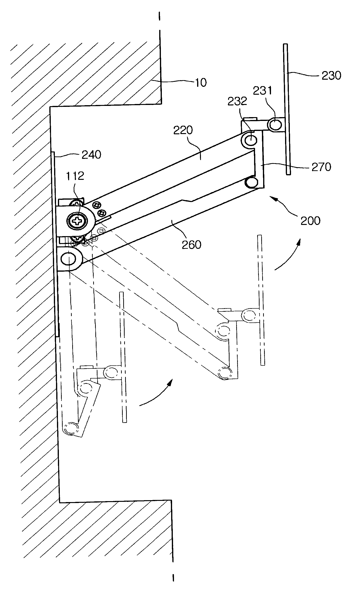
[0046]Therefore, a guide unit 200 is provided between the display device 30 and the door 10. When the display device 30 is advanced frontward by a predetermined distance and a predetermined angle, the view an...

second embodiment

[0090]This embodiment is substantially identical to the first embodiment except for the structure of the guide unit. Therefore, the description of the same parts will be omitted herein.

[0091]FIG. 11 shows a display device guiding apparatus according to a second embodiment of the present invention.

[0092]Referring to FIG. 11, a display device guiding apparatus according to this embodiment includes a fixing panel 310 fixed on the door, a fixing bracket 340 to which the display device is fixed, and a guide unit 300 interconnecting the fixing panel 310 and the fixing bracket 340. The guide unit 300 includes an arm assembly having opposite ends respectively hinge-coupled to the fixing panel 310 and the fixing bracket 340 and a spring 330 biasing the arm assembly 320 in a rotational direction.

[0093]A push button switch assembly is installed on a back cover of the display device 30 and the receiving portion 20 of the door 10 to maintain the initial state where the display device 30 is recei...

third embodiment

[0102]This embodiment is substantially identical to the first embodiment except that this embodiment has a feature where the display device can be effectively advanced frontward while overcoming the self-gravity. Therefore, the parts identical to those of the first embodiment will not be described herein.

[0103]FIGS. 13 and 14 show a display device guiding apparatus according to a third embodiment of the present invention.

[0104]Referring to FIG. 13, a back cover of a display device 30 is installed on a front surface of a fixing bracket 410 pivotable in multiple directions. A four-link articulated structure 420 is installed in a rear surface of the fixing bracket 410.

[0105]The articulated structure 420 includes a pair of parallel horizontal bars 422 having first and second ends respectively connected to a pair of vertical bars 424 by coupling screws 421 and 430. One of the vertical bars 424 is installed in a receiving portion 20 of a door 10.

[0106]A torsion spring 440 is installed on ...


PUM


Abstract

A display device guiding apparatus includes a receiving portion in which a display device can be received and a guide unit provided between the display device and the receiving portion. The guide unit includes a hinge assembly for pivoting the display at a predetermined angle, an arm assembly having first and second ends respectively connected to the hinge assembly and the receiving portion, and a pivot control unit providing a pivotal force of the arm assembly with respect to the receiving portion.

Description

[0001]This application claims the benefit of Korean Application No. 100663 / 2004 filed on Dec. 2, 2004, the entire disclosure of which is hereby incorporated by reference as if fully set forth herein.BACKGROUND OF THE INVENTION[0002]1. Field of the Invention[0003]The present invention relates to a refrigerator and an apparatus for guiding the displacement of a display device installed on a door of the refrigerator. Particularly, the present invention relates to a display device guiding apparatus of a refrigerator, which can prevent a display device mounted on the refrigerator from interfering with an outer wall and other components of the refrigerator by preventing the display device from being inclined in a direction when the display device pivots rightward and leftward, thereby allowing the display device to be smoothly projected frontward. More particularly, the present invention relates to a refrigerator and a display device guiding apparatus of the refrigerator, which allow a us...

Claims


Application Information

Patent Timeline
Patent Type & Authority Patents(United States)
IPC IPC(8): F25B49/00
CPCF16M11/04F16M11/10F16M11/12F16M11/2064F16M11/2092F16M11/24F25D29/005F16M2200/044F16M2200/065F25D2400/36Y10S248/919F25D23/00F25D23/02
Inventor LEE, YOUN SEOKKIM, YANG GYUOH, JOON HWAN
Owner LG ELECTRONICS INC
Learn More