Sensor mounting structure allowing for adjustment of sensor position

a technology for mounting structures and sensors, applied in the field of sensing devices, can solve the problems of insufficient standardization of supporting structures or other related structures/devices to allow for sensing devices, the desired arrangement of sensing devices, and the difficulty of installing sensing devices

Inactive Publication Date: 2009-06-16
ROCKWELL AUTOMATION TECH
View PDF61 Cites 12 Cited by
  • Summary
  • Abstract
  • Description
  • Claims
  • Application Information

AI Technical Summary

Benefits of technology

[0009]The present inventor has recognized that a variety of improved mounting devices or mechanisms for mounting sensing devices to supporting structures could be developed. More particularly, the present inventor has recognized that, in at least some embodiments, such mounting devices could employ a first component for supporting a sensing device, a second component to be mounted onto a supporting structure, and a third component for connecting the first component to the second component in a manner that allowed for some relative movement between the first and second components. The present inventor further has recognized that, in at least some additional embodiments, one or more adjustment component(s) could be added to the assembly to allow for controlled adjustment of the positioning of the first and second components in relation to one another, thus allowing for controlled adjustment of the positioning of the sensing device in relation to the supporting structure.

Problems solved by technology

Although in many circumstances it is desirable for a sensing device to be mounted in a manner such that the position of the sensing device is accurately fixed or at least limited to being within a predictable or predetermined range, it is often difficult to install sensing devices such that the sensing devices are mounted in this manner.
Consequently, mounting a sensing device onto a supporting structure by way of a simple procedure (e.g., simply attaching the sensing device to the supporting structure by way of bolts or screws) often does not result in a desired arrangement of the sensing device.
Although in some applications multiple sensing devices are intended to be respectively mounted on respective components of the same type in largely the same manner, in such cases there often still is insufficient standardization of the supporting structures or other related structures / devices to allow for the sensing devices to be mounted in a repetitive manner on the multiple structures without fine adjustment of the positioning of the individual sensing devices.
Indeed, it is often the case that the supporting structures on which sensing devices are to be mounted are not designed or manufactured to the tolerances that should be satisfied in the positioning of the sensing devices to allow for proper operation of those sensing devices.
Yet such conventional mounting mechanisms are limited in terms of their capabilities.
In some cases, such conventional mounting mechanisms only allow very slight adjustments in the positioning of sensing devices relative to the supporting structures on which the sensing devices are being mounted via the mounting mechanisms.
Also, the designs of many conventional mounting mechanisms make it difficult for persons installing sensing devices to achieve specific desired positions, that is, to finely adjust the positions of the sensing devices and set or lock the sensing devices in those positions.
Also, in some cases, even if during installation it is possible to achieve a specific desired position, it often is not possible or easy for the person doing the installing (or other persons) to determine that the desired position has been achieved.

Method used


Image

  • Sensor mounting structure allowing for adjustment of sensor position
  • Sensor mounting structure allowing for adjustment of sensor position
  • Sensor mounting structure allowing for adjustment of sensor position

Examples


Embodiment Construction

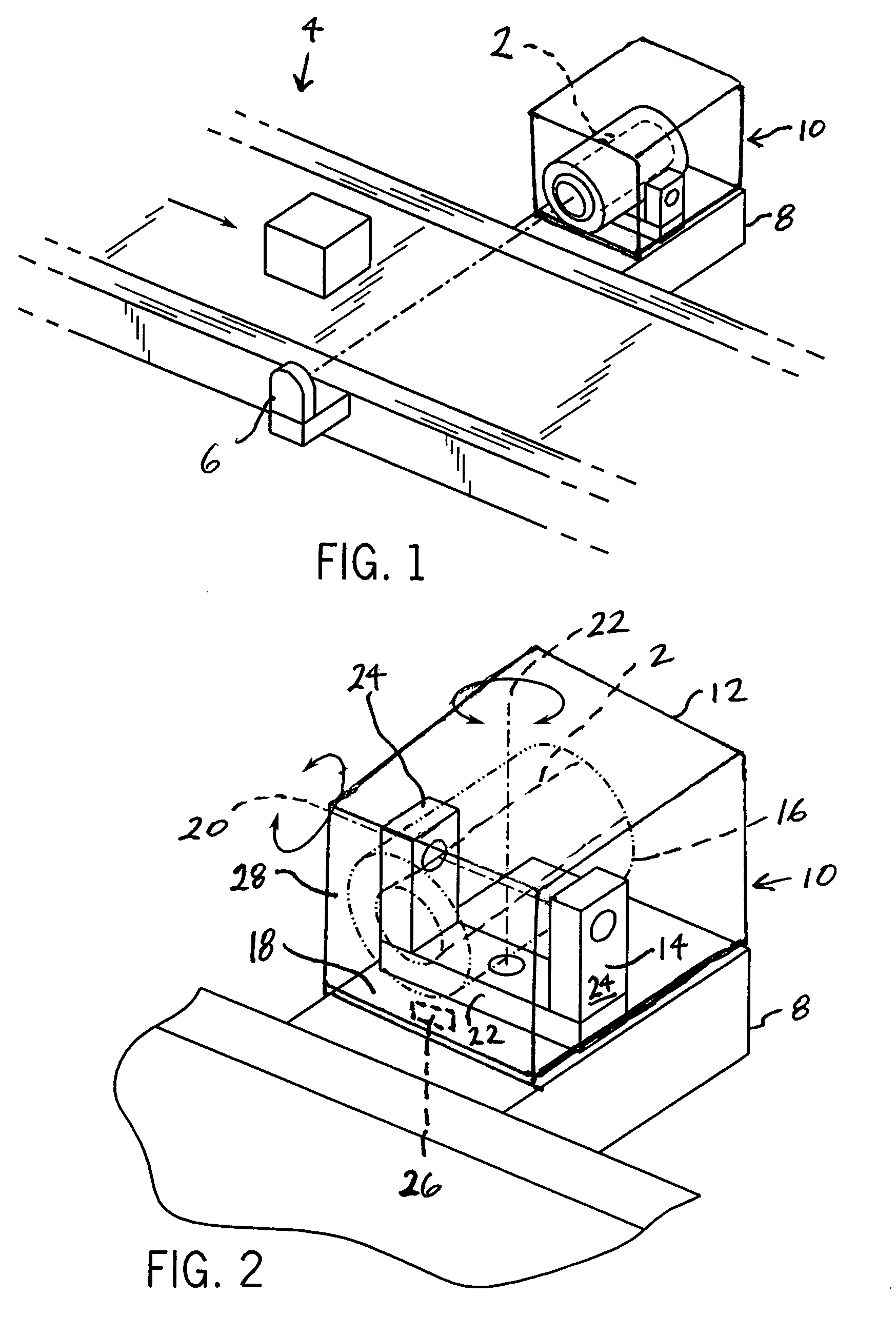
[0031]Referring to FIG. 1, a sensing device 2 is shown to be implemented in one exemplary application, namely, a conveyor system 4 as is often found in manufacturing and other commercial facilities implemented in assembly lines or the like. The sensing device 2 in the present embodiment is a light sensing device capable of receiving and detecting the presence of a light beam (e.g., a laser beam) emitted by a light source 6 located on the opposite side of the conveyor system 4. As shown, the sensing device 2 in particular is mounted onto a supporting structure 8 of the conveyor system 4 by way of a mounting mechanism 10. As discussed in further detail below with respect to the other FIGS., the mounting mechanism 10 can take a variety of forms in accordance with a variety of embodiments of the present invention.

[0032]Exemplary applications for the light sensing device arrangement of FIG. 1 can include, for example, “transmitted beam” or “through beam” applications. However, other appl...


PUM

PropertyMeasurementUnit
shapeaaaaaaaaaa
axial lengthaaaaaaaaaa
circumferenceaaaaaaaaaa

Abstract

A mounting device configured for mounting a sensing device in relation to a supporting structure, and related method of mounting, are disclosed. In at least some embodiments, the mounting device includes a first support component capable of being mounted at least indirectly in relation to the supporting structure, a second support component configured to support the sensing device, and a connecting component coupled between the first and second support components, where the connecting component supports the second support component in relation to the first support component. Also, the mounting device includes an adjustor coupled to at least one of the first support component, the second support component and the connecting component that influences a positioning of the second support component in relation to the first support component.

Description

CROSS-REFERENCE TO RELATED APPLICATIONSSTATEMENT REGARDING FEDERALLY SPONSORED RESEARCH OR DEVELOPMENTFIELD OF THE INVENTION[0001]The present invention relates to sensing devices and, more particularly, relates to various mechanisms, structures and / or methods for mounting sensing devices onto other structures.BACKGROUND OF THE INVENTION[0002]Sensing devices of many different types are commonly employed in a variety of environments and applications. Sensing devices encompass a broad spectrum of devices including, for example, various light-sensing devices such as laser-sensing devices, light sensing devices that are capable of distinguishing among different colors of visible light, and devices for sensing various other types of radiation including infrared radiation or heat, microwave radiation, and x-ray radiation. Additionally, other sensing devices include, for example, devices that are capable of sensing the position of other structures, acoustic sensors, vibration sensors, motio...

Claims


Application Information

Patent Timeline
Patent Type & Authority Patents(United States)
IPC IPC(8): G01D11/00
CPCG01D11/30H03K17/94H03K17/9505H03K2017/9455
Inventor SANTOS, ROBERTO S.
Owner ROCKWELL AUTOMATION TECH
Why Eureka
Try Eureka