Protective-field adjustment of a manipulator system

a manipulator and protection field technology, applied in the direction of manipulators, general control systems, instruments, etc., to achieve the effect of accurate control

Active Publication Date: 2018-11-15
KUKA ROBOTER
View PDF14 Cites 2 Cited by
  • Summary
  • Abstract
  • Description
  • Claims
  • Application Information

AI Technical Summary

Benefits of technology

[0028]More preferably, an adjustment signal can control the adjustment of a protective field at a defined position of the manipulator system. For this purpose, an adjustment signal can be transmitted, for example, once to the manipulator system, and specifications include when or where the adjustment of a protective field is to be made. In consideration of the current position of the manipulator system, which can be determined continuously, for example, by means of GPS technology, the initiation of the adjustment of a protective field

Problems solved by technology

An unknown obstacle can be an object, which was not considered at th

Method used


Image

  • Protective-field adjustment of a manipulator system
  • Protective-field adjustment of a manipulator system
  • Protective-field adjustment of a manipulator system

Examples


Embodiment Construction

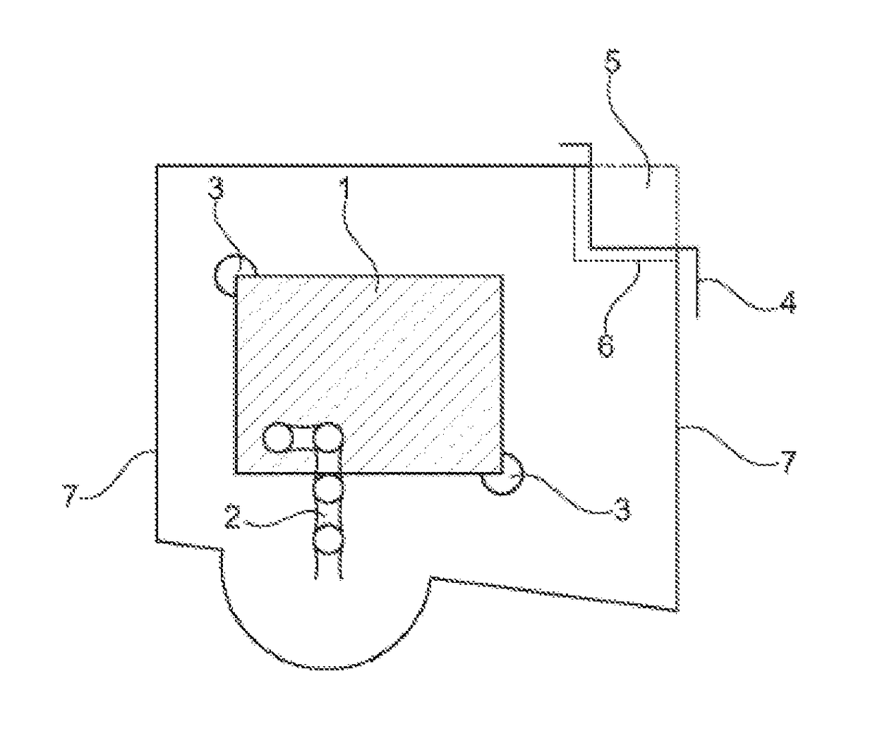
[0045]FIG. 1 shows a manipulator system, which comprises a driverless transport system 1 and a manipulator 2 mounted thereon. At the driverless transport system 1, two laser scanners 3 are provided, which monitor a protective field 7. Objects, which are present in the protective field 7, cause protective field infringements. These infringements can be output as binary signals, causing an emergency stop or other reactions of the manipulator system.

[0046]Further, in FIG. 1 an obstacle 4 is shown, which can be, for example, a wall. The obstacle 4 is, in particular, a known obstacle in the environment of the manipulator system. This obstacle is thus known and can be marked or identified in an environment map. According to the invention, a region 5 covered by the obstacle is cut based on this environment map. Thereby, this results in the illustrated protective field boundary 6, which runs along the contour of the obstacle 4.

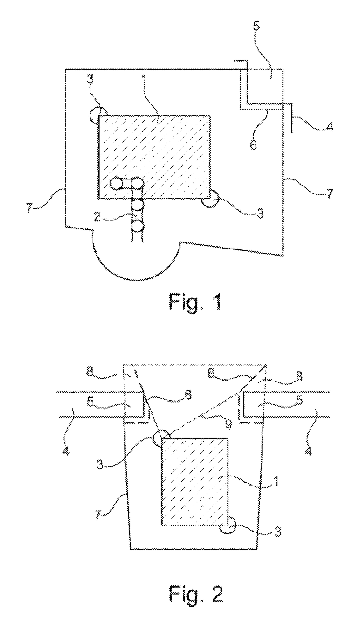
[0047]FIG. 2 also shows a driverless transport system 1, in whic...


PUM


Abstract

A method for operating a manipulator system, that includes a driverless transport system having a driverless transport vehicle. A protected field of the manipulator system is monitored by a monitoring device. Environment information of the manipulator system, including for example an orientation, position, movement, and/or state of an object or an obstacle in the environment, is obtained and used to adjust the protected field.

Description

1. TECHNICAL FIELD[0001]The present invention relates to a method for operating a manipulator system, which in particular can include a driverless transport system, and wherein a protective field of the manipulator system is monitored by a monitoring device. Further, the invention relates to a relevant manipulator system.2. TECHNICAL BACKGROUND[0002]Driverless transport systems (DTS) are often used in manufacturing facilities in order to transport, for example, components or workpieces from one work station to the next work station. A driverless transport system can have its own drive and is automatically controlled. Driverless transport systems can also be used to move manipulators or industrial robots, so that it can perform certain work-steps at different workstations.[0003]In general, a driverless transport system can be considered as a conveying system, which can comprise at least one driverless transport vehicle. The vehicle can thereby be multi-directionally and, in particula...

Claims


Application Information

Patent Timeline
IPC IPC(8): B25J9/16B25J19/06F16P3/14
CPCB25J9/1676B25J19/06F16P3/144G05B2219/49138
Inventor MAGNANIMO, VITOWALTHER, STEFFEN
Owner KUKA ROBOTER
Why Eureka
Try Eureka