

Driving circuit and a power converter incorporating the same
- Summary
- Abstract
- Description
- Claims
- Application Information
AI Technical Summary
Benefits of technology
Problems solved by technology
Method used
Image

Examples
Embodiment Construction
[0041]Before the present invention is described in greater detail, it should be noted that like elements are denoted by the same reference numerals throughout the disclosure.
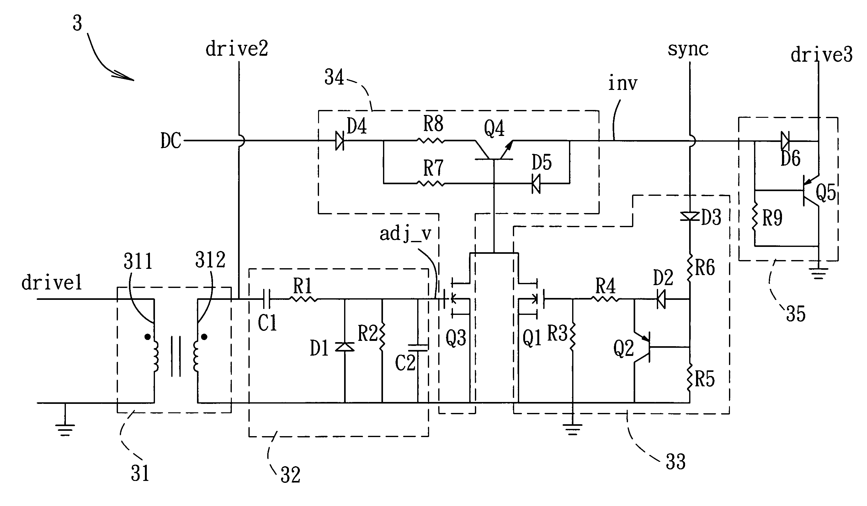
[0042]Referring to FIG. 3, the first preferred embodiment of a power converter according to the present invention is adapted to be connected electrically to an input power source 61 and an external load 62, and is adapted for receiving a driving signal (also referred to as the first driving signal (drive1)) that has high and low signal levels. In this embodiment, the first driving signal (drive1) is a pulse width modulation (PWM) signal, and the high and low signal levels are both steady state signal levels. The power converter includes an input circuit 1, a main transformer 21, a first switching circuit 41, a driving circuit 3, and a first output circuit 51.
[0043]The input circuit 1 includes a main switch 11 and a magnetic reset unit 12 connected in series to the main switch 11. The main switch 11 is operable i...
PUM
 Abstract
Description
Claims
Application Information