Mobile communication system, mobile communication method, mobile terminal and base station

Inactive Publication Date: 2009-06-16
NTT DOCOMO INC
View PDF18 Cites 17 Cited by
  • Summary
  • Abstract
  • Description
  • Claims
  • Application Information

AI Technical Summary

Benefits of technology

[0010]It is therefore an object of the present invention to provide a mobile communication system, a mobile communication method, a mobile terminal and a base station capable of realizing an effective power saving mode while reducing

Problems solved by technology

However, in the conventional art described above, during the power saving mode, the mobile terminal intermittently receives signals from the radio base stations or APs and recovers the communication state when the signals are received, so that in the case of making a transition to the communication state, a delay that is at most as much as the intermittent receiving period occurs since the signals are sent from the radio base station (AP) until the communication state is recovered.
For this reason, when a transition to the power saving mode is made during the realtime communications, a paging delay occurs and the packet receiving is not carried out normally so that there is a possibility for the quality degradation due to the packet loss.
In particular, in the cellular system described above, only one intermittent receiving period during the power savi

Method used


Image

  • Mobile communication system, mobile communication method, mobile terminal and base station
  • Mobile communication system, mobile communication method, mobile terminal and base station
  • Mobile communication system, mobile communication method, mobile terminal and base station

Examples


Example

[0025]Referring now to FIG. 1 to FIG. 6, the first embodiment of a mobile communication system according to the present invention will be described in detail.

[0026](Configuration of a Mobile Communication System)

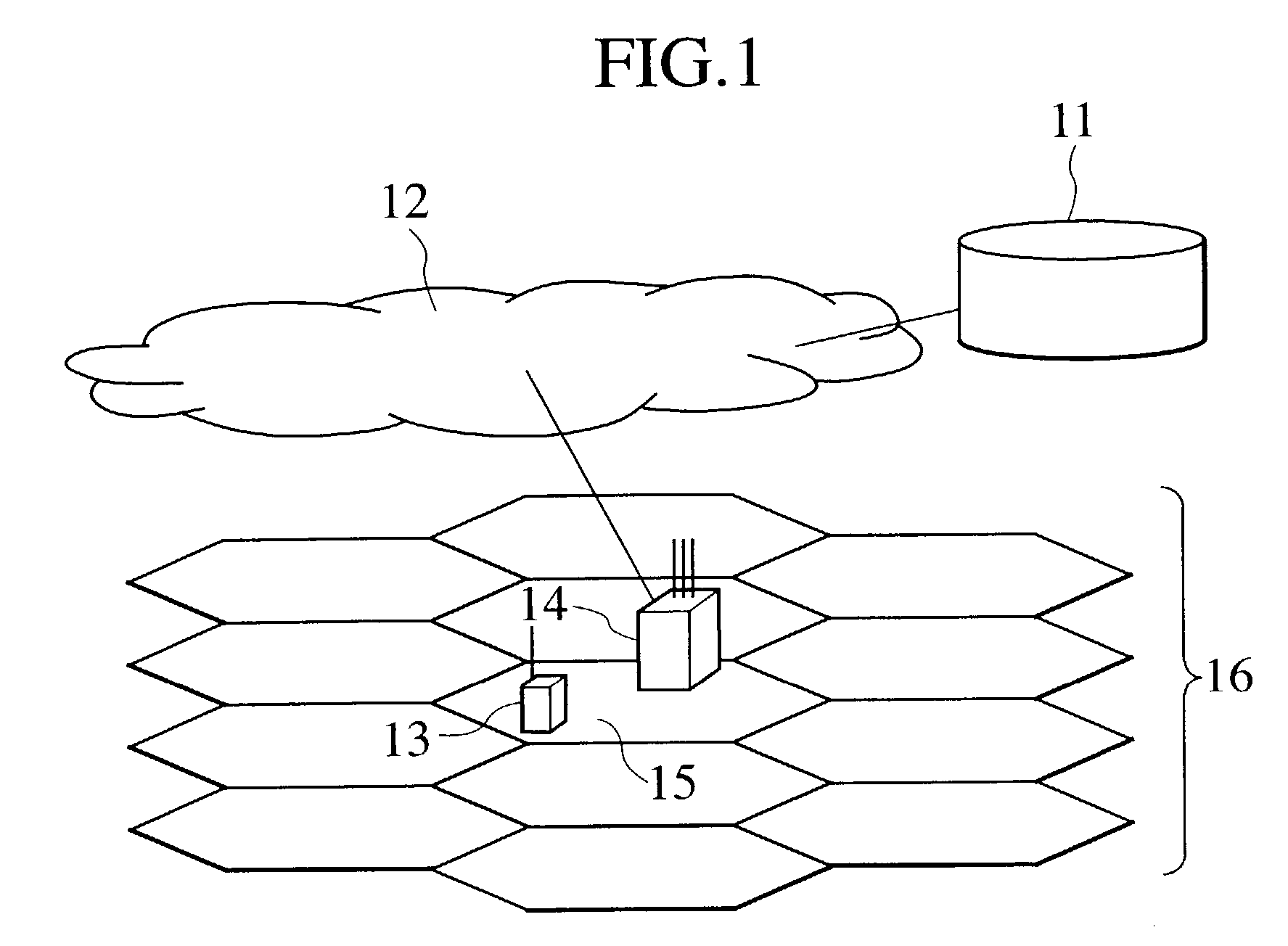
[0027]FIG. 1 schematically shows a basic configuration of the mobile communication system according to the first embodiment, which is also applicable to the second embodiment to be described below.

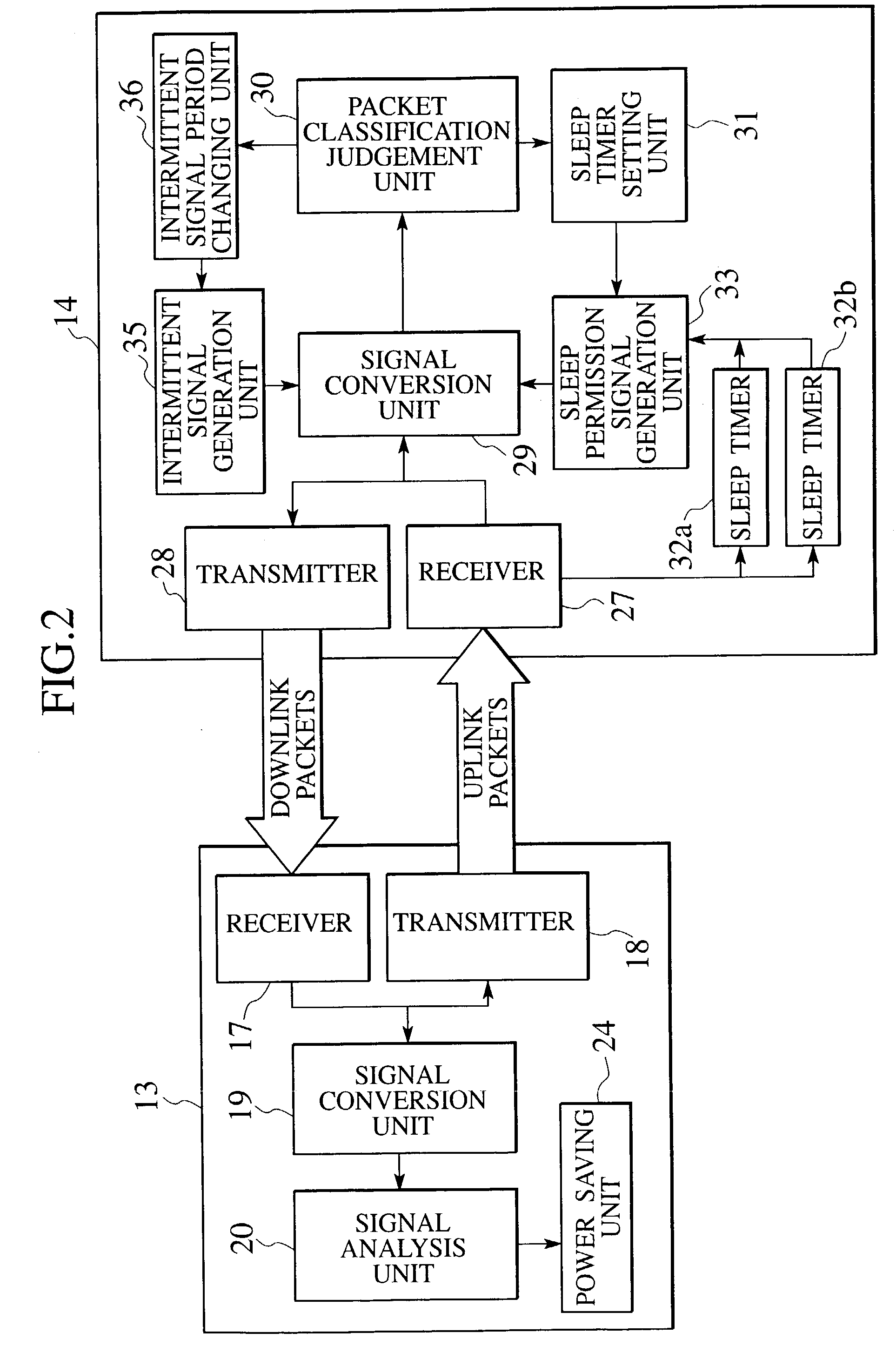
[0028]As shown in FIG. 1, the mobile communication system according to this embodiment has a communication network 12 formed by interconnecting communication channels, a mobile terminal 13 to be used by a user and connected to the communication network 12, a radio base station 14 for carrying out packet communications with the mobile terminal 13, and a location information management server 11 connected with the communication network 12, for managing a location information of the mobile terminal 13.

[0029]Each mobile terminal 13 is located within a cell 15 formed by the radio base s...

Example

Second Embodiment

[0066]Referring now to FIG. 7 to FIG. 9, the second embodiment of a mobile communication system according to the present invention will be described in detail.

[0067]This embodiment is characterized in that the packet classification judgement unit, the sleep timer setting unit, and the intermittent signal period changing unit as described above are provided on the mobile terminal side. FIG. 7 shows an internal configuration of the mobile terminal 53 according to this embodiment.

[0068]Namely, as shown in FIG. 7, the mobile terminal 53 has a transmitter 18, a receiver 17, a signal conversion unit 19, a packet classification judgement unit 20, a sleep timer setting unit 21, sleep timers 22a and 22b, a sleep timer execution unit 23, a power saving unit 24, an intermittent signal period determination unit 25, and a notification signal generation unit 26.

[0069]The transmitter 18 and the receiver 17 carry out transmission / reception of packet data and control signals with re...


PUM


Abstract

In a mobile communication system for carrying out packet transmission/reception between a mobile terminal having a power saving mode to reduce a power consumption and a radio base station, a packet type of a packet is judged, and a sleep timer value indicating a time duration since a last packet is transmitted/received until the power saving mode starts is set according to a judgement result. Then, at least one sleep timer for measuring an elapsed time since the packet is transmitted/received is activated, and the mobile terminal is controlled to execute the power saving mode at a timing at which the elapsed time measured by the at least one sleep timer exceeded the sleep timer value.

Description

BACKGROUND OF THE INVENTION[0001]1. Field of the Invention[0002]The present invention relates to a method for saving power in a mobile communication system, and more particularly, to a technique for a power saving mode transition on a mobile terminal in radio packet communications.[0003]2. Description of the Related Art[0004]Conventionally, the mobile communication system such as PHS or HIPERLAN Type 2 (High Performance Radio Local Area Network) is provided with a power saving mode function for reducing a battery consumption of a mobile terminal.[0005]For example, the cellular system such as PHS is a communication system of circuit switching type in which the end of communication is clear so that, after the communication is terminated, the mobile terminal makes a transition to a power saving mode for intermittently receiving signals from radio base stations. There is only one period for the intermittent receiving in this power saving mode called super-frame period (see ARIB RCR STD-...

Claims


Application Information

Patent Timeline
IPC IPC(8): H04B7/185H04M1/00H04B7/26H04M11/00H04W52/02
CPCH04W52/0229H04W52/0241H04W52/0248Y02B60/50Y02D30/70H04B7/26H04W52/02H04W88/02
Inventor MOTEGI, MASAYUKIKAYAMA, HIDETOSHIUMEDA, NARUMI
Owner NTT DOCOMO INC
Why Eureka
Try Eureka