
Kalman-viterbi joint channel equalizer

a technology of equalizer and channel, applied in the field of equalizer, can solve the problems of reducing the reception performance of a receiver such as a digital television, affecting neighboring symbols, and affecting the reception performance of the receiver, so as to achieve the effect of eliminating transmission errors and facilitating the resolution of distortion

Inactive Publication Date: 2009-06-16
ELECTRONICS & TELECOMM RES INST
View PDF14 Cites 28 Cited by
  • Summary
  • Abstract
  • Description
  • Claims
  • Application Information

AI Technical Summary

Benefits of technology

The fast Kalman-Viterbi joint channel equalizer significantly improves convergent speed and reduces residual errors, enhancing reception performance in dynamic multi-path environments by using soft-decision Viterbi decoding and Kalman gain calculations, even in the absence of training symbols.

Problems solved by technology

In the ATSC (Advanced Television Systems Committee) standard which has been adopted as a digital television broadcasting standard in North America, there is a problem in that transmission signals are distorted under an indoor and mobile communication environment due to variable channel and multi-path effects.
This reduces reception performance in a receiver such as a digital television.
This induces interference in the neighboring symbols.
In addition, transmitted data is affected by various kinds of channel distortions, caused by such effects as a multi-path effect, a frequency offset effect, a phase jitter effect, and so on.
Therefore, the ISI becomes a barrier to obtaining desired data in a receiver.
When a decision error is not generated in a quantization block of the DFE, noise amplification at output of the equalizer, which becomes a problem in a conventional linear equalizer, does not appear when a rear filter removes ISI due to a symbol determined previously.
However, not enough training symbols are inserted in most cases.
The conventional DFE does not have a rapid enough convergent speed to compensate for distortion of a received signal that is generated due to inter-channel interference under a highly distorted communication environment such as indoor reception, mobile reception, or in a communication environment producing ghost images such as a broadcasting channel.

Method used

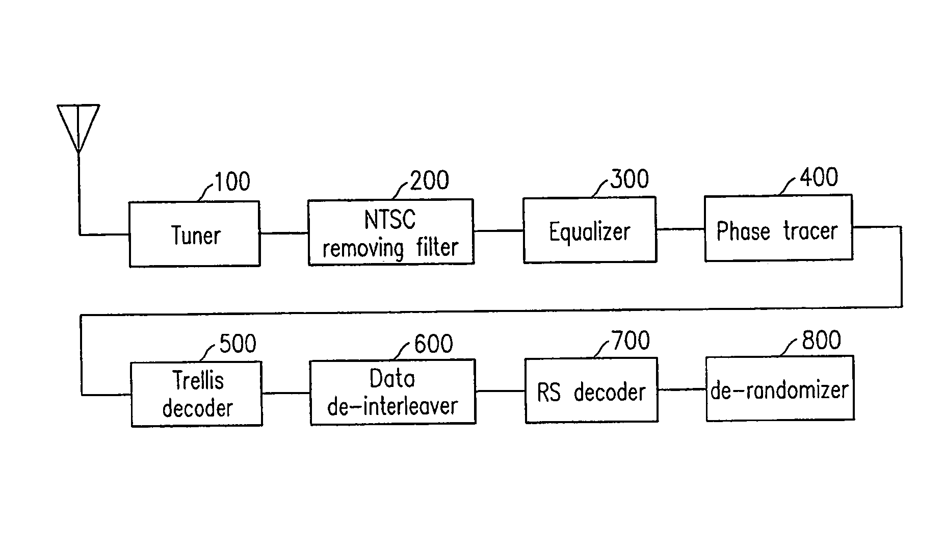
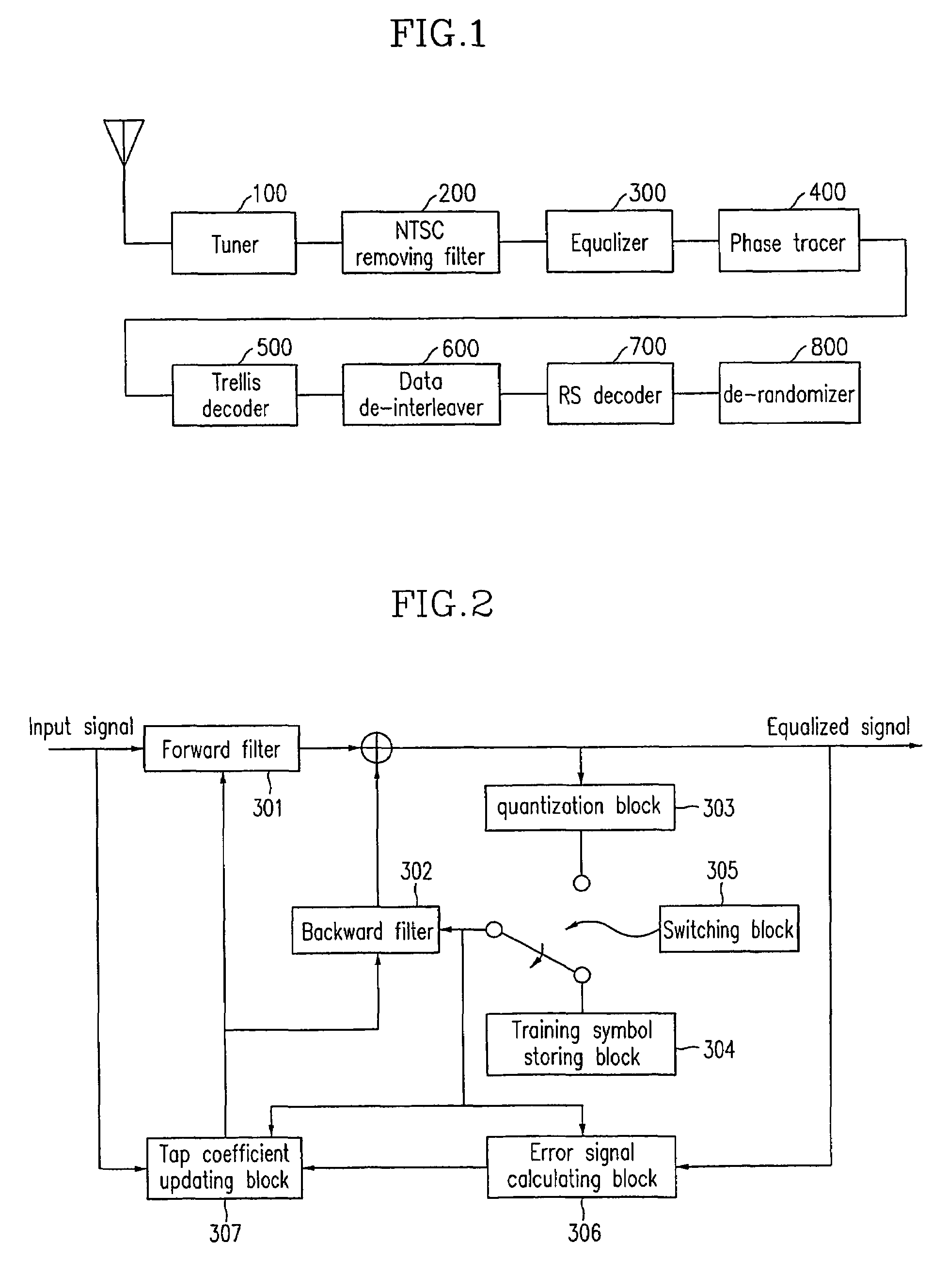

Image

  • Kalman-viterbi joint channel equalizer
  • Kalman-viterbi joint channel equalizer
  • Kalman-viterbi joint channel equalizer

Examples


Embodiment Construction

[0028]In the following detailed description, only the preferred embodiment of the invention has been shown and described, simply by way of illustration of the best mode contemplated by the inventor(s) of carrying out the invention. As will be realized, the invention is capable of modification in various obvious respects, all without departing from the invention. Accordingly, the drawings and description are to be regarded as illustrative in nature, and not restrictive.

[0029]At first, a fast Kalman algorithm will be described by referring to Falconer's paper in the following.

[0030]Various kinds of signals, filter coefficients, and other variables may be defined as below.

[0031]xN(n): input signal vector for overall filters

[0032]y(n): forward filter input signal sample

[0033]d(n): desired signal

[0034]xN(n)=[y(n−1), . . . y(n−N1)|d(n) . . . d(n−N2)]T

[0035]ξp(n)=[y(n)d(n)]T

[0036]ρp(n)=[y(n−N1)d(n−N2)]T

[0037]εp(n): forward preceding error

[0038]εp(n)′: forward following error

[0039]ANp(n)...


PUM


Abstract

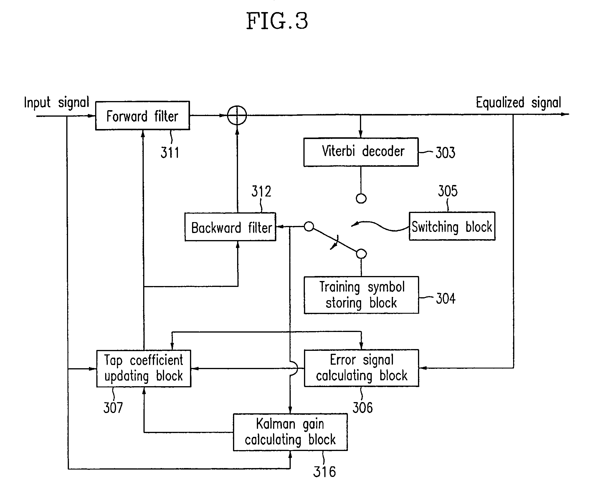
In a channel equalizer applicable to a digital television receiver, a forward filter and a backward filter perform filtering to an input signal and a predetermined signal. A Viterbi decoder corrects errors during a transmission procedure in a blind mode. A training symbol storing block stores training symbols. An output signal of the Viterbi decoder and symbols are provided to the backward filter in accordance with a blind mode or a training mode. A Kalman gain is calculated in a Kalman gain calculating block and an error signal is calculated by comparing an equalized signal, symbols, and the output signal of the Viterbi decoder with one another. A tap coefficient is updated by using the calculated error signal and the Kalman gain.

Description

BACKGROUND OF THE INVENTION[0001]The present patent application is a non-provisional application of International Application No. PCT / KR03 / 00779, filed Apr. 17, 2003.[0002](a) Field of the Invention[0003]The present invention relates to an equalizer and a control method of the equalizer which are used for improving performance in a receiver under a multi-path communication environment of indoor, portable, and mobile reception.[0004](b) Description of the Related Art[0005]In the ATSC (Advanced Television Systems Committee) standard which has been adopted as a digital television broadcasting standard in North America, there is a problem in that transmission signals are distorted under an indoor and mobile communication environment due to variable channel and multi-path effects. This reduces reception performance in a receiver such as a digital television.[0006]In a digital communication system, data transmission is performed in symbol units through a restricted frequency band width, a...

Claims


Application Information

Patent Timeline
Patent Type & Authority Patents(United States)
IPC IPC(8): H03H7/30G06F17/10H03H7/40H03K5/159H04N7/015H04L25/03H04N5/21H04N5/44H04N7/12
CPCH04L25/03057H04N5/211H04L2025/03375H04L2025/0349H04L2025/03617H04N5/4401H04N21/426H04N7/015H04N7/12
Inventor KIM, SUNG-HOONSIM, YONG-HUNKIM, SEUNG-WONAHN, CHIETEUKKIM, DAE-JIN
Owner ELECTRONICS & TELECOMM RES INST
Learn More