Method and device for capture, storage and recirculation of heat energy

a heat energy and heat storage technology, applied in the field of heat energy capture, storage and recirculation, can solve the problems of system inherently inefficient, system prone to structural damage, costly repairs, etc., and achieve the effects of high heat capacity, easy availability, and increased water temperatur

Inactive Publication Date: 2009-06-23
MOORMAN WILLIAM E
View PDF3 Cites 24 Cited by
  • Summary
  • Abstract
  • Description
  • Claims
  • Application Information

AI Technical Summary

Benefits of technology

[0026]The storage system underneath the building comprises a storage tank and means for the heated air to be directed into the storage tank. The storage tank is filled with water; the water serves to store the heat energy from the heated air. The heated air bubbles up through the water within the storage tank, transferring the heat from the air to the water, raising the temperature of the water. Once the air rises through the body of water within the tank, the air is exhausted into the crawl space under the building. The air exhausted into the crawl space heats the ground, foundation and floor of the building, and may also rise into the space within the structure through floor registers provided for that purpose. Because heated air rises, cooler air will remain within the crawl space to be vented to the atmosphere through louvered vents in the side of the foundation provided for that purpose. Water is utilized in the present invention due to its easy availability, high heat capacity, and use in a building's existing systems. Other equivalent liquids may be used, especially within the closed loop of a baseboard heating system. Those skilled in the art will recognize that closed loops within the storage tank may be utilized so that there is no mixing of fluids in the various heating systems of a building, such as the potable water system. Preferentially, however, water is utilized as a common liquid.

Problems solved by technology

This system is inherently inefficient in that the heat to be stored must be gathered by water at the roof, where the pipes carrying the liquid must be heated, and thence the water within the pipes.
The Heilemann system is not only inefficient to the extent that it requires a structurally and mechanically complicated system, but it is further undesirable in that the circulation of water in the system poses a significant threat of structural damage and costly repairs should part of the system fail.
In addition, the multiple processes required for the transfer of heat to the structure are sources of significant inefficiencies.
In addition, these preexisting systems do little to reduce the temperature of the liquid being circulated prior to the liquid being returned to the rooftop heat source.
Because the heat transfer into and out of the circulating liquid is limited, the capacity to capture more heat by the water is limited, thereby reducing the efficiency of the system.
However, the Gonzalez system provides at best an inefficient means to remove unwanted heat from the system or the structure itself; having a heat removal process is critical for efficient building climate control.
Without forced air flow to counteract the natural rise of heated air, heated air within the Gonzalez solar panels will collect and become trapped inside the solar panel structure.
There is also no means of utilizing natural air flow mechanisms to capture, store, and vent heated air.
Finally, the Gonzalez invention is inherently inefficient in that it only provides limited control in response to seasonal variations in ambient temperature.
None of these previous inventions provide means for enhancing the heat collection at the roof of a structure.
Nor do they provide an efficient means for the collection and storage of the heat energy collected.
The Heilemann, Diggs, and Gonzalez inventions, the heat storage means does not provide efficient means for removing the heat energy from the circulated heat collecting medium.
Nor do any of the systems make full utilization of heat trapped in storage means, such as a water storage tank, where such heated water may be utilized for heat and hot water supply.

Method used


Image

  • Method and device for capture, storage and recirculation of heat energy
  • Method and device for capture, storage and recirculation of heat energy
  • Method and device for capture, storage and recirculation of heat energy

Examples


Embodiment Construction

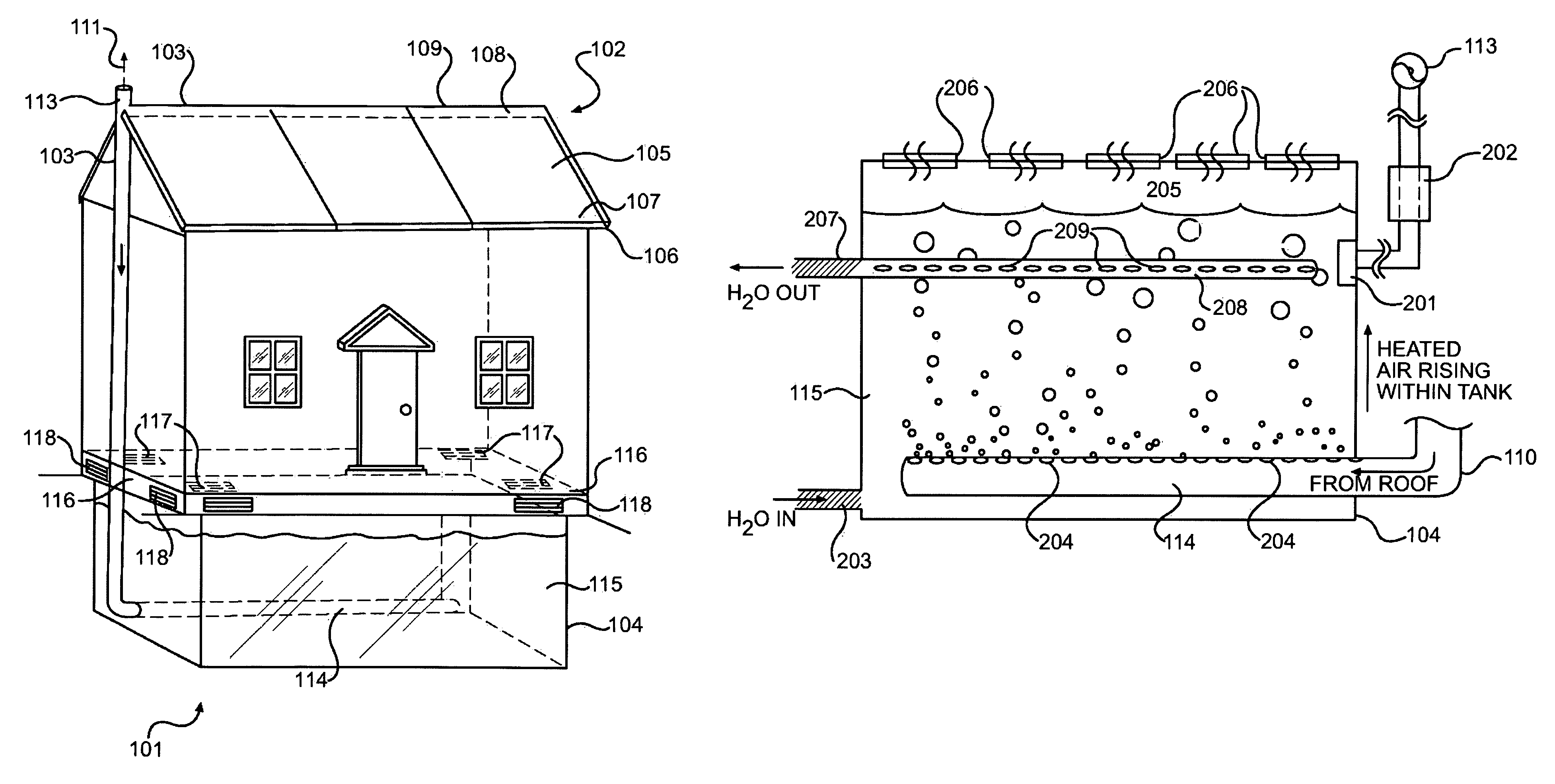
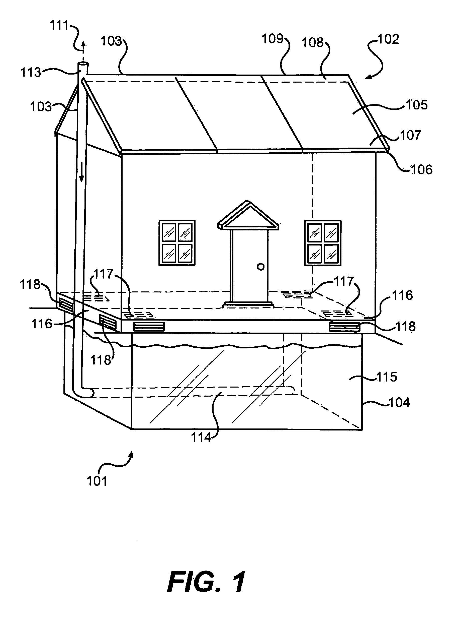
[0032]Referring to FIG. 1 of the drawings, a heat storage system 101 comprising a rooftop heat generation and collection apparatus 102, heated air transport apparatus 103, and heat storage tank 104 is shown as incorporated into a building. The rooftop heat generation and collection apparatus 102 comprises roof panels 105 which are located above the surface of the roof 106. The roof panels 105 are substantially transparent and while various materials may be utilized for the roof panels 105, it is preferred that lightweight transparent or semi-transparent materials, such as Plexiglas® and the like, form the basis for the roof panels 105. The surface of the roof 106 is preferentially colored or coated with a non-reflective and / or black surface. In one such embodiment, heavy-gauge black plastic is used as a roof covering. It is also preferable that the spaces located underneath the roof structure are insulated; commonly available insulation materials may be utilized to insulate the stru...


PUM


Abstract

A heat generation and storage device supplements building heating and hot water systems. A roof cap including an air passage is connected to air outlets disposed within the roof structure of a building and to air passages formed by panels mounted over the surface of a building's roof. The roof cap is connected to a vent which either exhausts air to the atmosphere and/or recirculates air to a liquid heat storage tank. Heated air and heated water from the storage tank supplement a building's heating and hot water systems.

Description

[0001]This Application claims the benefit of U.S. application Ser. No. 11 / 764,215 filed on Jun. 17, 2007.BACKGROUND OF THE INVENTION[0002]1. Field of the Invention[0003]This invention relates to the capture, storage and recirculation of heat energy in residential and commercial buildings. The present invention is intended to be incorporated into new construction, although the present invention may be utilized in pre-existing buildings as well. In general, the present invention provides means to capture, store, and recirculate heat generated within a structure, and more specifically provides for the storage of heat energy that is generated or collected at or near the highest point of a structure. Heated air is generated at the roof of a building due to natural processes and / or design features incorporated into a building's structure. The heated air is redirected into a storage facility beneath a structure, and the storage facility utilizes the heated air to warm a body of water that ...

Claims


Application Information

Patent Timeline
Patent Type & Authority Patents(United States)
IPC IPC(8): F24J2/46
CPCF24D11/003F24F5/0096F24J2/045F24J2/20F28D20/0034F28D20/0043F28C3/06F24F2005/0025F24F2005/0064Y02B10/24Y02B10/20Y02E10/44Y02E60/142F24S10/50F24S20/67Y02E60/14Y02A30/272Y02A30/60
Inventor MOORMAN, WILLIAM E.
Owner MOORMAN WILLIAM E
Why Eureka
Try Eureka