Pixel shifting color projection system

a color projection and color technology, applied in the field of projection systems, can solve the problems of color wheel waste, color wheel light loss, color wheel wasting, etc., and achieve the effects of enhancing resolution, reducing mechanical motion, and increasing resolution

Inactive Publication Date: 2009-06-23
THOMSON LICENSING SA
View PDF21 Cites 70 Cited by
  • Summary
  • Abstract
  • Description
  • Claims
  • Application Information

AI Technical Summary

Benefits of technology

[0008]The present invention provides a projection system for projecting a full-color image using a micro-display with reduced mechanical motion and/or increased resolution. In an exemplary embodiment, the projection system has an integrator with an output end having a matrix of output windows therein. An imager modulate

Problems solved by technology

Existing DLP imagers, however, suffer from several problems.
The color wheel wastes light, as the light having the colors that are reflected is typically lost.
Also, color separation or break-up artifacts degrade the image quality

Method used


Image

  • Pixel shifting color projection system
  • Pixel shifting color projection system
  • Pixel shifting color projection system

Examples


Embodiment Construction

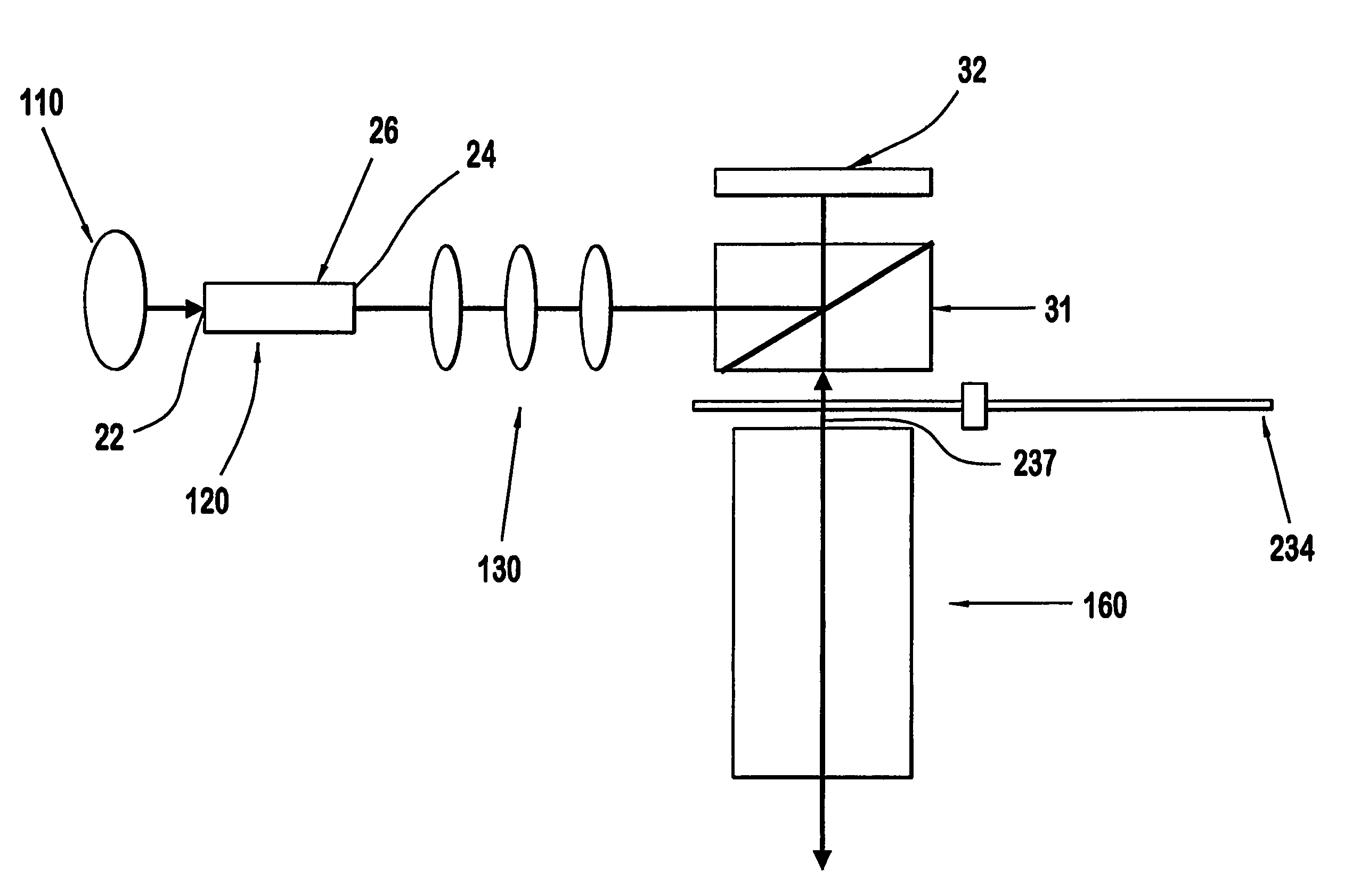
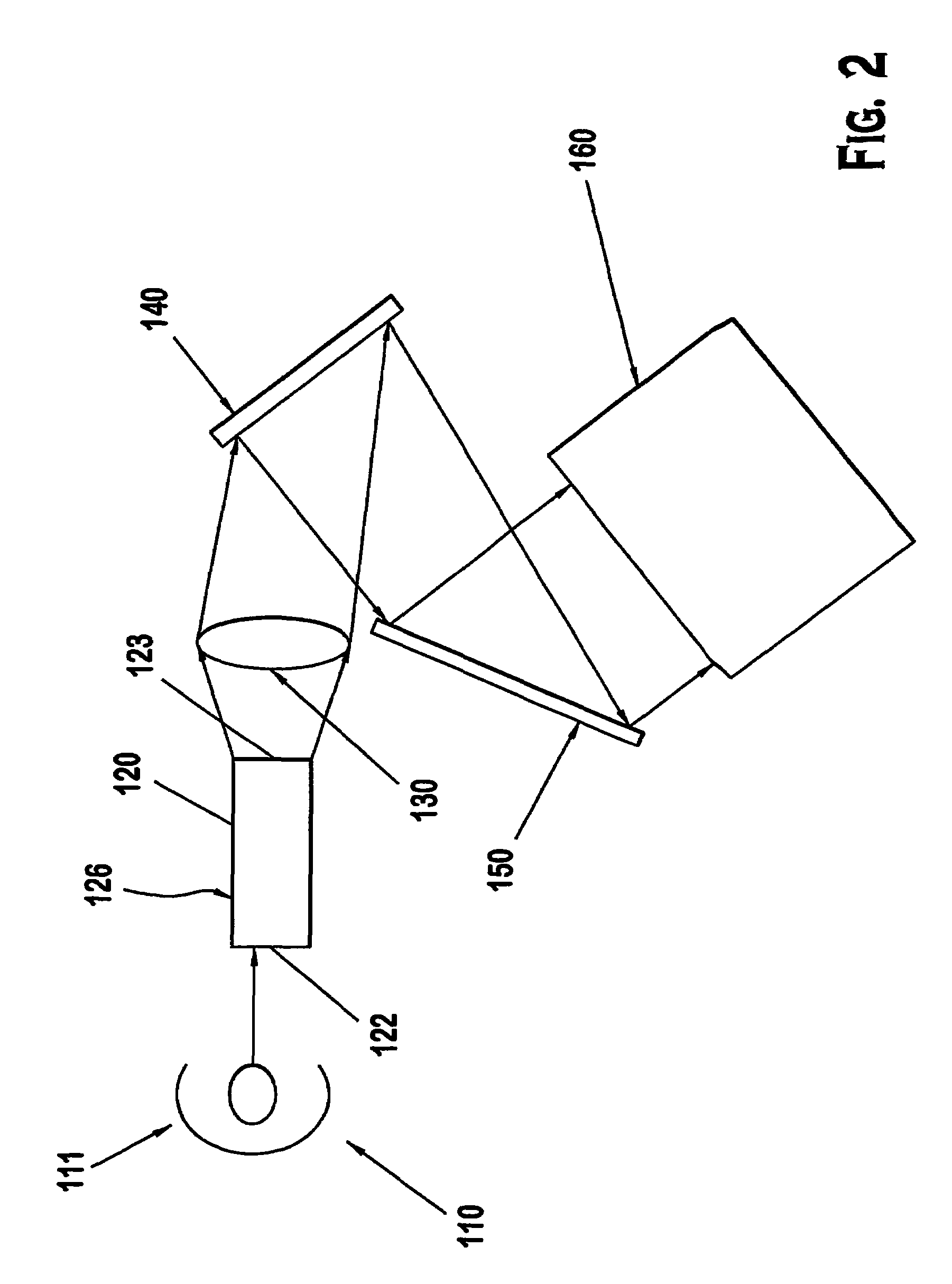
[0021]The present invention provides a color projection system, such as for a television display, for projecting a video image with enhanced resolution and / or reduced mechanical motion of the projection system due to shifting of a pattern of monochromatic pixels. In an exemplary embodiment, as shown in FIG. 2, white light is generated by a lamp 110 and directed into an integrator 120 by a parabolic reflector 111. In an exemplary embodiment, the lamp 110 is a high intensity multiple wavelength output lamp which is suitable for use in projection display systems. A suitable lamp 110 for this purpose is a UHP lamp that is well known in the art as a light source for projection displays. Light output of the lamp 110 is coupled to an integrator 120. The integrator 120 is a formed as a rectangular cylinder for directing light output of the lamp toward an imager 140 in a given rectangular aspect ratio and size which corresponds with that of the imager 140. In this embodiment, the integrator ...


PUM


Abstract

A projection system including an integrator with an output end having a matrix of output windows therein. A pattern of red, green and blue monochromatic filters are disposed on the output windows passing a matrix of red, green, and blue monochromatic pixels of light. An imager modulates the pixels of monochromatic light A light shift device shifts the matrix of monochromatic pixels of light to temporally form a pattern of overlying pixels of light of different colors, viewable as a color image.

Description

CROSS-REFERENCE TO RELATED APPLICATIONS[0001]This application claims the benefit, under 35 U.S.C. § 365 of International Application PCT / US2004 / 034270, filed Oct. 15, 2004, which was published in accordance with PCT Article 21(2) on Apr. 28, 2005 in English and which claims the benefit of U.S. provisional patent application No. 60 / 511,801, filed Oct. 16, 2003; U.S. provisional patent application No. 60 / 511,958, filed Oct. 16, 2003; and U.S. provisional patent application No. 60 / 511,872, filed Oct. 16, 2003.FIELD OF THE INVENTION[0002]The invention is related generally to a projection system, and more particularly to a projection system including micro-displays wherein a pattern of discrete color pixels is shifted.BACKGROUND[0003]Micro-display projection systems using a reflective light engine or imager, such as digital light pulse (DLP) imager, are increasingly utilized in color image or video projection devices (e.g., rear projection television (RPTV)). In an existing projection sy...

Claims


Application Information

Patent Timeline
IPC IPC(8): G03B21/28H04N9/31
CPCH04N9/3114H04N9/3197G03B21/208H04N9/31
Inventor WILLIS, DONALD HENRYBEYERS, BILLY WESLEYHALL, JR., ESTILL THONEDEISS, MICHAEL SCOTT
Owner THOMSON LICENSING SA
Why Eureka
Try Eureka