
Device for the supply of a gas

a technology for gas supply and devices, applied in medical devices, medical science, surgery, etc., can solve the problems of deteriorating capability and unintentional total compression of devices, and achieve the effects of large flexibility, large bendability of supplies, and reduced flexibility

Inactive Publication Date: 2009-06-23
CARDIA INNOVATION
View PDF15 Cites 6 Cited by
  • Summary
  • Abstract
  • Description
  • Claims
  • Application Information

AI Technical Summary

Benefits of technology

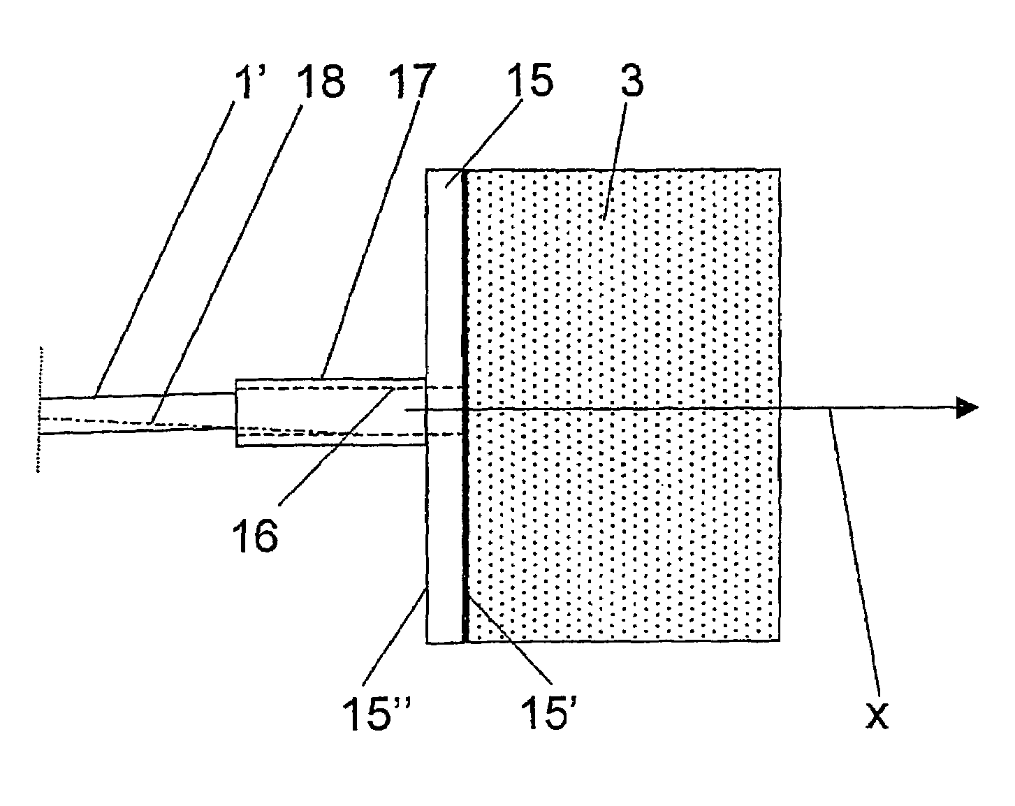
[0007]By such an attachment member, a sufficiently large surface may be created for attaching the porous body in a secure manner. Furthermore, the porous body will be kept stretched during use so that unintentional total compression thereof is made significantly more difficult. However, it is also possible to manually compress the porous body by pressing it axially towards the surface of the attachment member and in such a way press out a liquid, for instance blood, from the porous body. A large quantity of liquid in the body may deteriorate its capability of providing a laminar gas flow. By such an attachment member, also the outflow direction or outflow directions of the gas supplied through the porous body will be guided, for instance to flow outwardly from the body forwardly and laterally. A rearward flow may for instance be prevented in an efficient manner. By such an attachment member, also less turbulence may be obtained in the volume to which the gas is supplied. The attachment member and the porous body may be manufactured with small dimensions and thus be provided very close to or in said area.
[0008]According to an embodiment of the invention, said surface of the attachment member covers substantially the whole porous body seen in a first direction extending from the attachment member through the body. In such a way, gas is efficiently prevented from flowing rearwardly from the porous body. However, the surface may also have a smaller extension and permit a certain rearward flow.
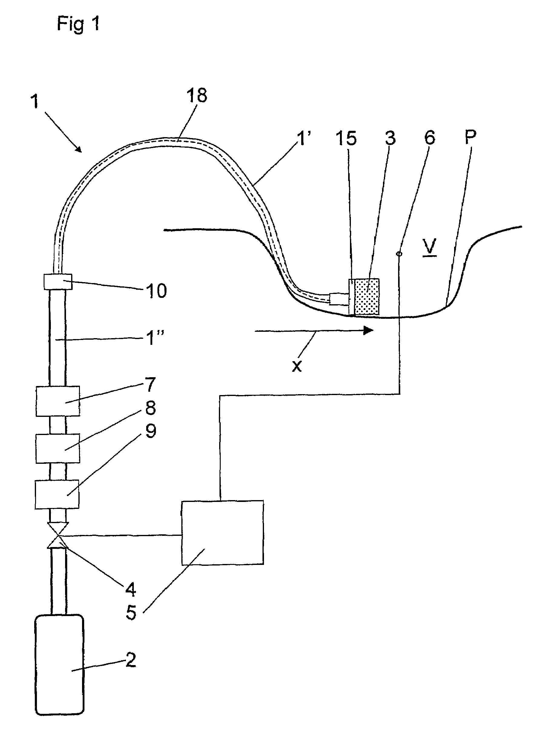
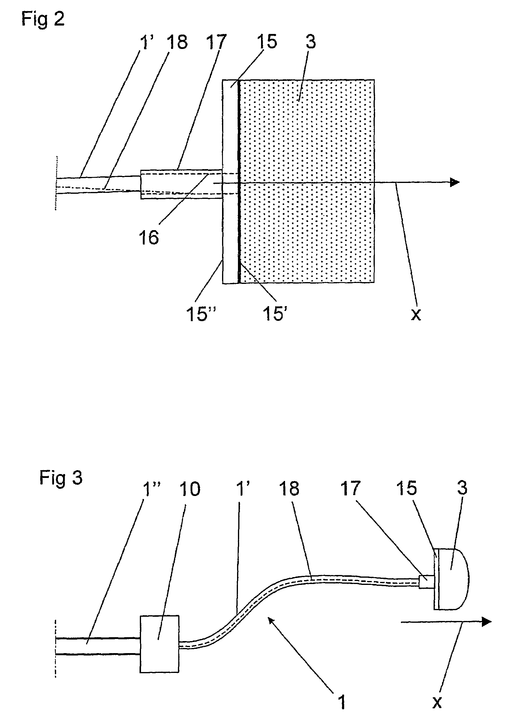
[0011]According to a further embodiment of the invention, the supply conduit includes at least a first conduit portion with a casing of a material, which has a large flexibility, and with a means for stiffening, which extends along the casing and has a lower flexibility than the casing. By means of such a construction, a large bendability of the supply conduit is obtained in such a way that it may be bent to any shape permitting the body to be positioned in a advantageous manner in said volume. Furthermore, the stiffening means permits the supply conduit to maintain the shape obtained during use of the device. Thus the stiffening means may be plastically deformable and may for instance include a metal wire. Furthermore, the stiffening means may advantageously extend substantially freely within the supply conduit and more precisely within the first conduit portion.

Problems solved by technology

Furthermore, the porous body will be kept stretched during use so that unintentional total compression thereof is made significantly more difficult.
A large quantity of liquid in the body may deteriorate its capability of providing a laminar gas flow.

Method used


Image

  • Device for the supply of a gas
  • Device for the supply of a gas
  • Device for the supply of a gas

Examples


Embodiment Construction

[0020]FIGS. 1 and 2 disclose a device according to a first embodiment of the invention. The device disclosed is intended to create a protecting atmosphere in an area which here is exemplified by a concave volume V adjoining a temporary open, inner portion P of a human being in order to prevent air from the surroundings from reaching the volume V. It is to be noted that the area and thus the inner portion P also may be substantially plane or even slightly convex. Such an open portion P is formed during operations performed in an open manner, i.e. when an inner portion P of the body is uncovered for the performance of the surgical operation. In connection with for instance heart surgery, a substantial part of the interior of the thorax is uncovered so that this normally has direct contact with the surrounding atmosphere, i.e. with air. However, it is to be noted that the device according to the invention may be applied in many different contexts for the supply of gas to various volume...


PUM


Abstract

A device for supply of a gas to a volume includes a supply conduit, which is connectable to a gas source and which includes an outlet end, and a porous body, which is provided at the outlet end.The device is arranged to permit the supply of the gas through the porous body. The device includes an attachment member which includes a surface and a channel extending through the surface. The porous body is attached to the surface and the outlet end is connected to the attachment member in order to permit the supply via the channel.

Description

THE BACKGROUND OF THE INVENTION AND PRIOR ART[0001]The present invention refers to a device for the supply of a gas. Such a device is disclosed in the previous application of the applicant, WO01 / 45790.[0002]During surgery, which is performed in an open manner, i.e. when an inner portion of the body is uncovered for the performance of the surgical operation, it can be important to prevent air from the surroundings to reach the open portion of the body in order to avoid infections, for instance. Such infections may be caused by microorganisms and bacteria, which are always present in the surrounding air and which fall down towards the open portion of the body. It is thus desirable to create a protecting atmosphere around the open portion in order to protect said inner portion from non-sterile air and also falling particles. In addition, different surgical operations may involve various requirements on the protecting atmosphere. In this connection it is referred to WO01 / 45790, which di...

Claims


Application Information

Patent Timeline
Patent Type & Authority Patents(United States)
IPC IPC(8): A61M37/00A61B19/00A61G13/00
CPCA61B19/38A61G13/108A61B2019/385A61B2090/401A61B90/40
Inventor VAN DER LINDEN, JANPERSSON, MIKAEL
Owner CARDIA INNOVATION
Learn More