
Computer camera system and method for reducing parallax

Inactive Publication Date: 2009-06-23
MICROSOFT TECH LICENSING LLC
View PDF156 Cites 7 Cited by
  • Summary
  • Abstract
  • Description
  • Claims
  • Application Information

AI Technical Summary

Benefits of technology

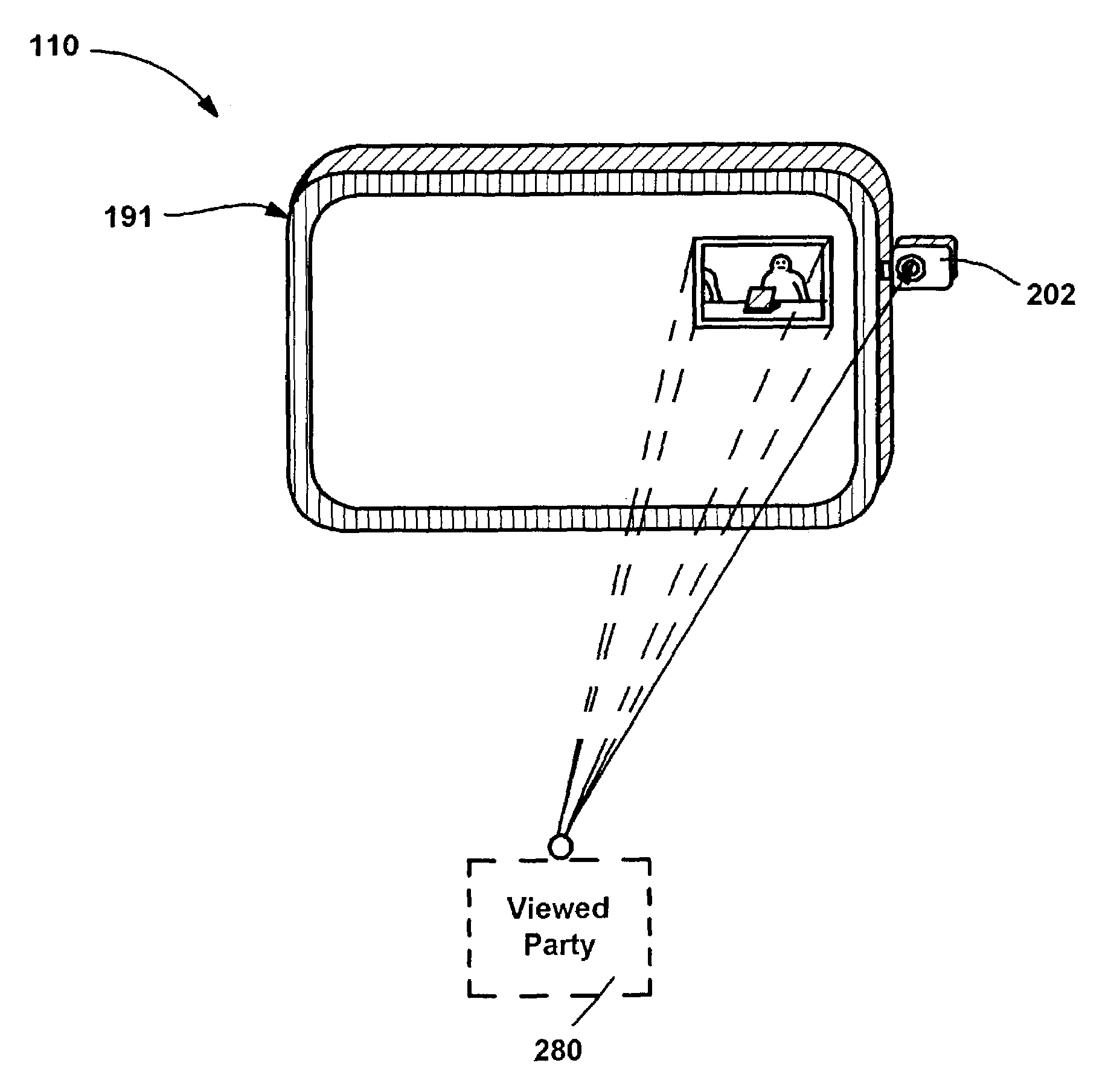
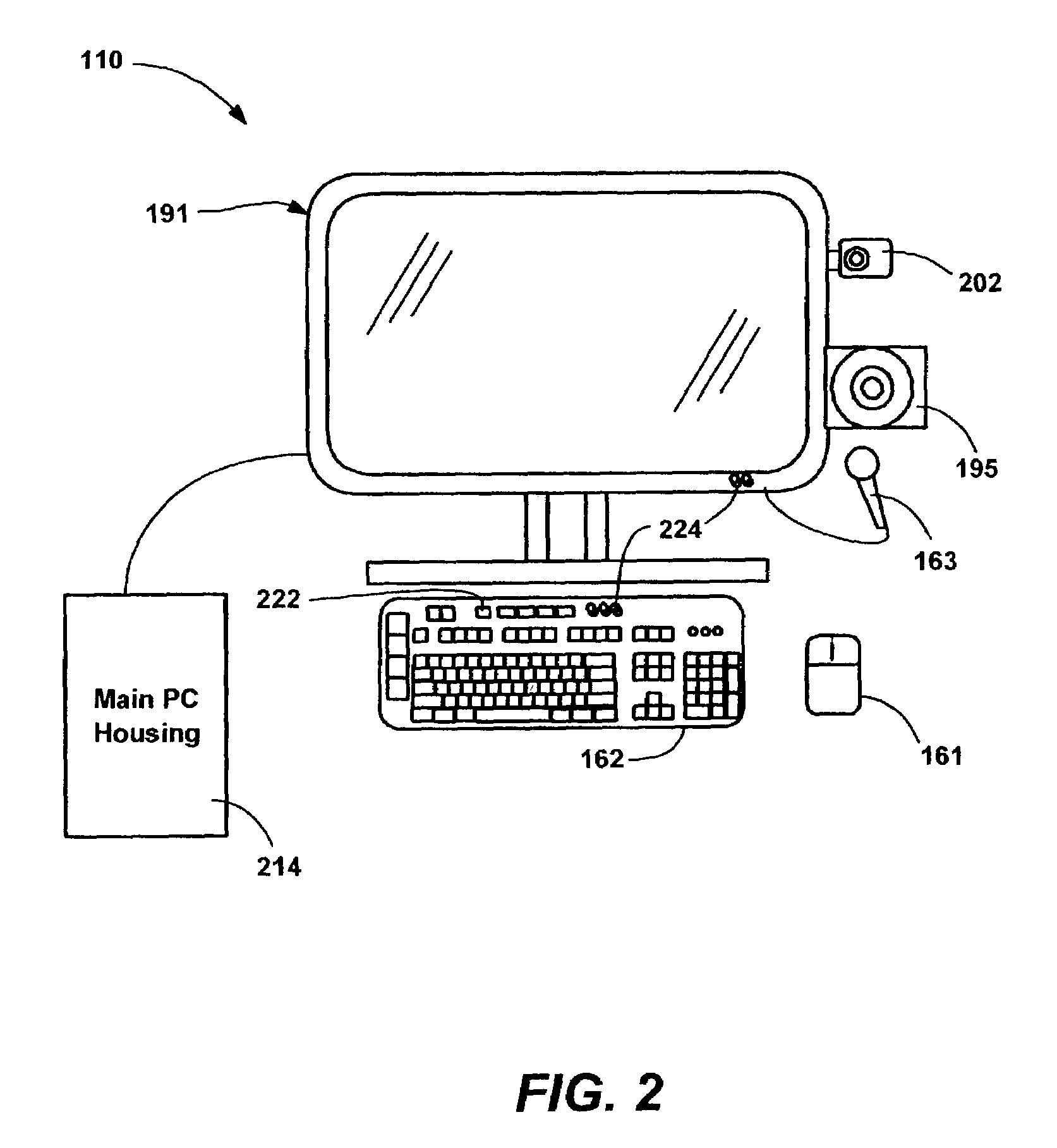
[0014]Briefly, the present invention provides a camera mounted on a computer system in a manner that decreases the parallax that causes an unnatural looking video communication. In one implementation, this is on the side of the monitor so that eyes are level with the camera, rather than looking down as with conventional top-mounted cameras. Further, the focal point of the user that is being viewed, such as the counterpart displayed video image from a participant in the communication, may be positioned near the camera, such that the user tends to look in the general direction of the camera while communicating.
[0016]In one alternative embodiment, a participant receiving video in a video communication may control the position of a displayed image on another participant's monitor to minimize the perceived parallax. To this end, in addition to possibly controlling the sender's camera zoom, pan, focus and / or other effects from the recipient's end, the recipient can send data to the sender that effectively guides the eyes of the other party to a location that the recipient viewer prefers the other party to generally look towards. This may be a counterpart video image sent to the other party, a document on which both parties are collaborating, or some other item of interest.

Problems solved by technology

One of the difficulties with computer video cameras is making the video over IP experience seem natural.
Sometimes, however, the problems with providing a natural-looking presentation are not solely with the communications technology, but rather are with the way that the participants act or appear while on camera.

Method used


Image

  • Computer camera system and method for reducing parallax
  • Computer camera system and method for reducing parallax
  • Computer camera system and method for reducing parallax

Examples


Embodiment Construction

Exemplary Operating Environment

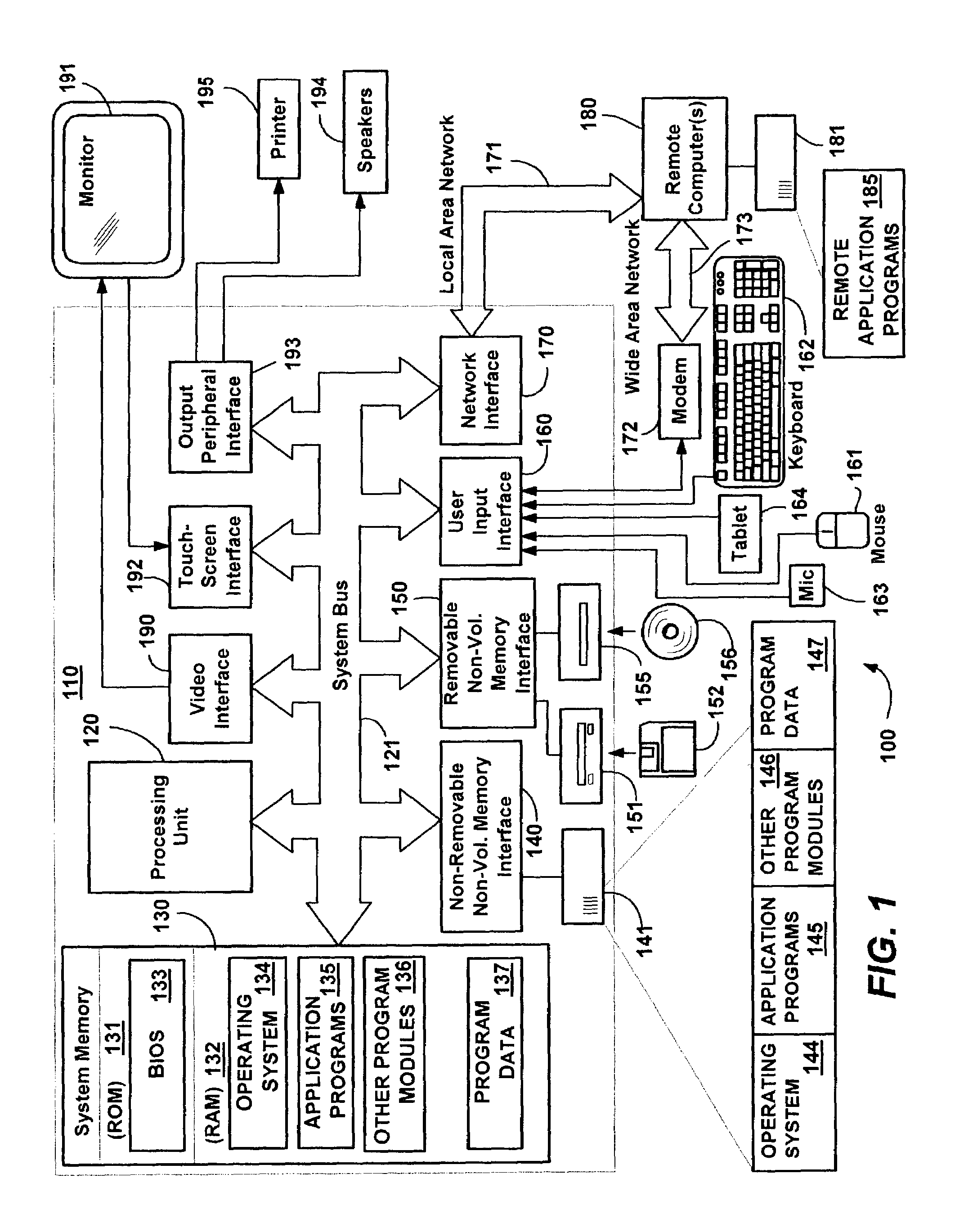
[0028]FIG. 1 illustrates an example of a suitable computing system environment 100 on which the invention may be implemented. The computing system environment 100 is only one example of a suitable computing environment and is not intended to suggest any limitation as to the scope of use or functionality of the invention. Neither should the computing environment 100 be interpreted as having any dependency or requirement relating to any one or combination of components illustrated in the exemplary operating environment 100.

[0029]The invention is operational with numerous other general purpose or special purpose computing system environments or configurations. Examples of well known computing systems, environments, and / or configurations that may be suitable for use with the invention include, but are not limited to: personal computers, server computers, hand-held or laptop devices, tablet devices, multiprocessor systems, microprocessor-based systems, set ...


PUM


Abstract

A camera mounted on a computer system such as on a side of a monitor or behind a displayed image to reduce the parallax that results from a camera viewing angle that differs from a viewed party's viewing angle of a display, and that causes unnatural looking video communications. An item of interest corresponding to a focal point of the user that is being viewed, such as a counterpart displayed video image from a participant in the communication, may be positioned near the camera, such that the user tends to look in the general direction of the camera while communicating. Camera movement may be sensed to facilitate automatic or manual repositioning of the displayed item of interest, and a participant, such as a remote participant receiving video in a video communication may control the position of a displayed image on the monitor to minimize the parallax.

Description

CROSS-REFERENCE TO RELATED APPLICATIONS[0001]The present invention is related to the following co-pending United States Patent Applications filed concurrently herewith, assigned to the assignee of the present invention, and hereby incorporated by reference in their entireties:[0002]“Method and System for Auxiliary Display of Information for a Computing Device,” U.S. application Ser. No. 10 / 052,039, filed Jan. 17, 2002;[0003]“Real-Time Communications Architecture and Methods for use with a Personal Computer System,” U.S. application Ser. No. 10 / 429,905, filed May 5, 2003;[0004]“Record Button on a Computer System,” U.S. application Ser. No. 10 / 429,904, filed May 5, 2003;[0005]“Method and System for Auxiliary Processing Of Information for a Computing Device,” U.S. application Ser. No. 10 / 429,930, filed May 5, 2003;[0006]“System and Method for Activating a Computer System,” U.S. application Ser. No. 10 / 430,369, filed May 5, 2003;[0007]“Computer System with Do Not Disturb System and Meth...

Claims


Application Information

Patent Timeline
IPC IPC(8): H04N7/14H04N5/225
CPCH04N7/142H04N7/144
Inventor BEAR, ERIC GOULDMAGENDANZ, CHADADAMS, ADITHA MAYLEDBETTER, CARLKANEKO, STEVE
Owner MICROSOFT TECH LICENSING LLC
Learn More