Cooling mechanism for circuit board

a cooling mechanism and circuit board technology, applied in the direction of insulated conductors, power cables, cables, etc., can solve the problems of reducing cooling efficiency, affecting the surrounding electronic products, and leakage of electromagnetic radiation noise produced by the electronic components on the circuit board, so as to prevent the leakage of electromagnetic radiation noise, improve the cooling efficiency of electronic components, and effectively shield electromagnetic radiation noise

Inactive Publication Date: 2009-06-23
KYOCERA DOCUMENT SOLUTIONS INC
View PDF18 Cites 6 Cited by
  • Summary
  • Abstract
  • Description
  • Claims
  • Application Information

AI Technical Summary

Benefits of technology

[0009]An object of the present invention is to accomplish the space-saving, simply and inexpensively improve the cooling efficiency of electronic components on a board and effectively shield electromagnetic radiation noises in a cooling mechanism for a circuit board using a cooling fan.
[0010]In order to accomplish this object, one aspect of the present invention is directed to a cooling mechanism for a circuit board, comprising a board having electronic components disposed thereon; one or more heat radiation plates to be disposed on the board; a cooling fan for cooling the board and the electronic components disposed on the board by blowing air to at least one of the heat radiation plates; and a metal plate attached to one end of the board to ground the board, thereby preventing the leakage of electromagnetic radiation noises from the electronic components, wherein the metal plate includes a bent portion bent in L-shape along a lateral side of the board, the cooling fan is so disposed at the inner side of the bent portion as to be perpendicular to the board, and an air receiving surface of the heat radiation plate is so arranged as to be oblique to an axial blowing direction of the cooling fan.
[0011]According to this construction, the cooling fan is securely fixed, utilizing the bent portion of the metal plate. Further, the metal plate for preventing the leakage of noises and the cooling fan can be mounted on the board in a compact manner. Thus, the heat production and the leakage of electromagnetic noises from the circuit board can be simply and inexpensively suppressed. Further, the circuit board can be efficiently cooled by guiding the blown air to the heat radiation plates and the electronic components located at positions distanced from the axial blowing direction of the cooling fan. Furthermore, since there is no need for wiring that is required if the cooling fan is a separate part, it becomes easier to mount the cooling fan on the board and to mount the board in an apparatus main body.

Problems solved by technology

On the other hand, there is a possibility that electromagnetic radiation noises produced by the electronic components on the circuit board leak to the outside and influence electronic products around.
Therefore, there have been problems of reducing cooling efficiency due to longer distances between the cooling fan and the circuit boards and enlarging the apparatus to provide an air blowing path.
Thus, a positional relationship between the cooling fan and the heat radiation plates or the respective electronic components cannot be sufficiently rationalized, whereby the heat radiation plates cannot be always disposed on the air blowing path.
Therefore, there is a problem of being unable to obtain a sufficient cooling effect.
In either case, such a space hinders the miniaturization and the space-saving of the apparatus.

Method used


Image

  • Cooling mechanism for circuit board
  • Cooling mechanism for circuit board
  • Cooling mechanism for circuit board

Examples


Embodiment Construction

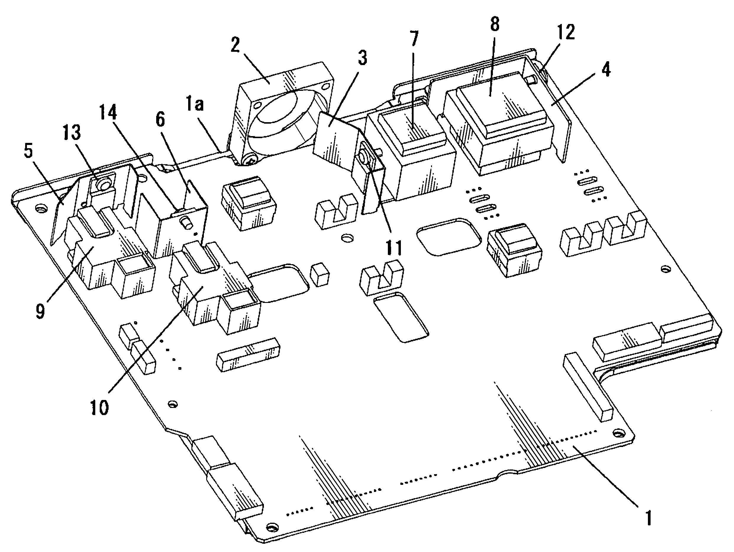
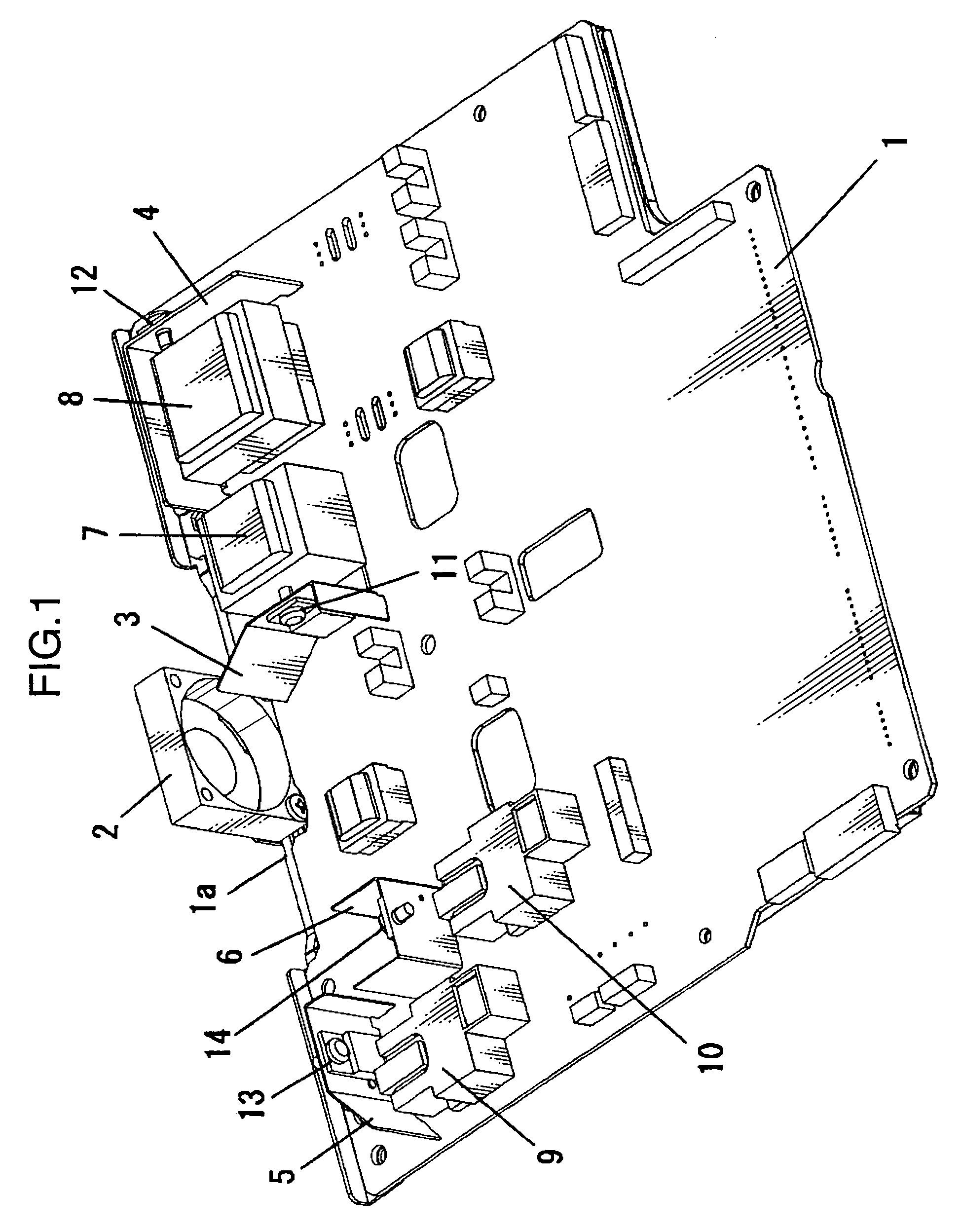
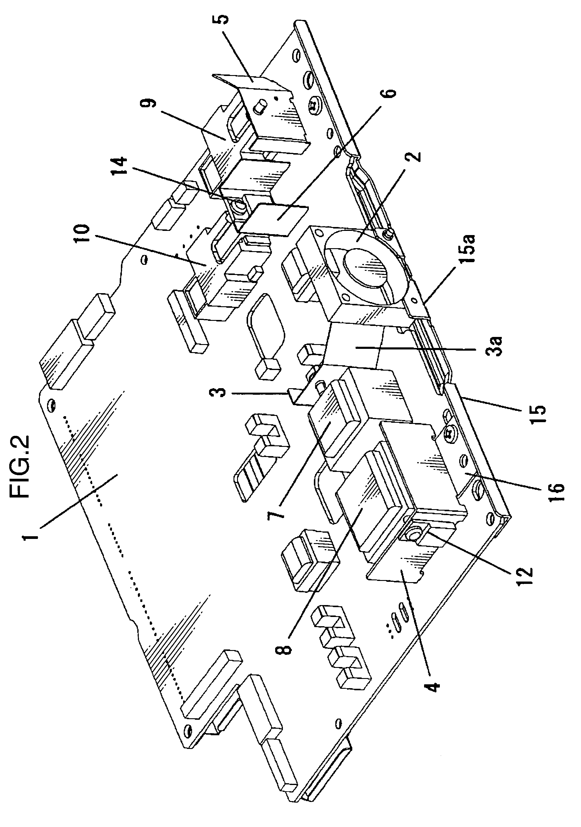
[0020]Hereinafter, embodiments of the present invention are described with reference to the accompanying drawings. FIGS. 1 and 2 are schematic perspective views showing one example of a circuit board provided with a cooling mechanism according to a first embodiment of the invention. This cooling mechanism includes a board 1 having various electronic components disposed thereon, a cooling fan 2 for cooling the electronic components by blowing air to the electronic components, and a noise preventing metal plate 15 for preventing the leakage of electromagnetic radiation noises from the electronic components.

[0021]The board 1 is a substantially rectangular flat board and has a notch 1a in the form of a shallow recess at an intermediate portion of one side edge. The cooling fan 2 is disposed in the notch 1a. Metallic heat radiation plates 3, 4, 5, 6 for radiating heats produced from the electronic components on the board 1 and transformers 7, 8, 9, 10 for converting an alternating-curren...


PUM

PropertyMeasurementUnit
angleaaaaaaaaaa
angleaaaaaaaaaa
heataaaaaaaaaa

Abstract

A cooling mechanism for a circuit board includes a board having electronic components disposed thereon, one or more heat radiation plates disposed on the board, a cooling fan for cooling the board and the electronic components disposed on the board by blowing air to at least one of the heat radiation plates, and a metal plate attached to one end of the board to ground the board, thereby preventing the leakage of electromagnetic radiation noises from the electronic components. Further, the metal plate includes a bent portion bent in L-shape along a lateral side of the board, and the cooling fan is so disposed at the inner side of the bent portion as to be perpendicular to the board. Furthermore, an air receiving surface of the heat radiation plate is so arranged as to be oblique to an axial blowing direction of the cooling fan.

Description

BACKGROUND OF THE INVENTION[0001]1. Field of the Invention[0002]The present invention relates to a cooling mechanism for a circuit board used in an electronic apparatus provided with a plurality of electronic components and particularly to a mechanism for cooling the respective electronic components using a cooling fan.[0003]2. Description of the Background Art[0004]In electronic apparatuses such as copiers, personal computers and televisions, various circuit boards each having a plurality of electronic components mounted on a board are used. Since such circuit boards generally produce heat as the electronic apparatus operate, a cooling mechanism needs to be provided so as not to cause deterioration and damage of the electronic components due to heat production. Conventionally, a cooling mechanism adopting natural heat radiation by attaching a metallic heat radiation plate to each electronic component and radiating heat into the air after transferring the heat of the electronic comp...

Claims


Application Information

Patent Timeline
Patent Type & Authority Patents(United States)
IPC IPC(8): H05K7/20F28F7/00H01B7/42
CPCG06F1/20H05K7/20172
Inventor ITOH, SHINJI
Owner KYOCERA DOCUMENT SOLUTIONS INC
Why Eureka
Try Eureka