Fluid cooled electronic assembly

a technology of electronic assemblies and fluid cooling, applied in the field of electronic assemblies, can solve problems such as electrical circuit failure and performance reduction

Active Publication Date: 2009-06-23
DELPHI TECH IP LTD
View PDF33 Cites 64 Cited by
  • Summary
  • Abstract
  • Description
  • Claims
  • Application Information

AI Technical Summary

Problems solved by technology

Excessive heat build-up may cause reduced performance including electrical circuit failure.

Method used


Image

  • Fluid cooled electronic assembly
  • Fluid cooled electronic assembly
  • Fluid cooled electronic assembly

Examples


first embodiment

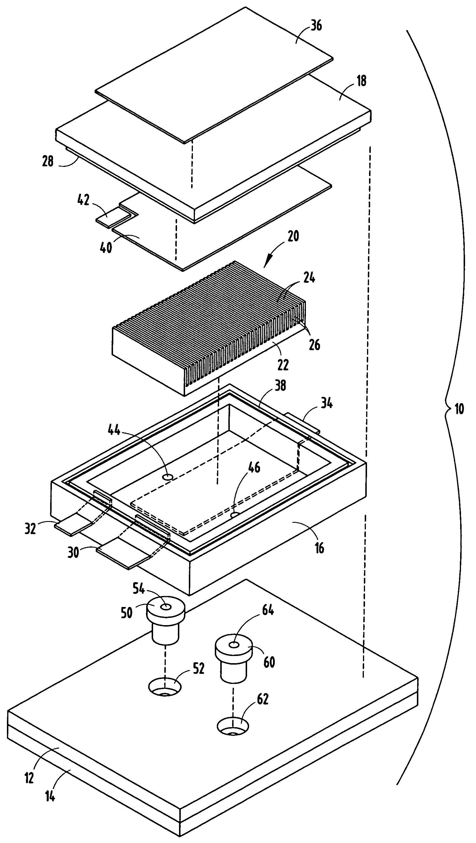
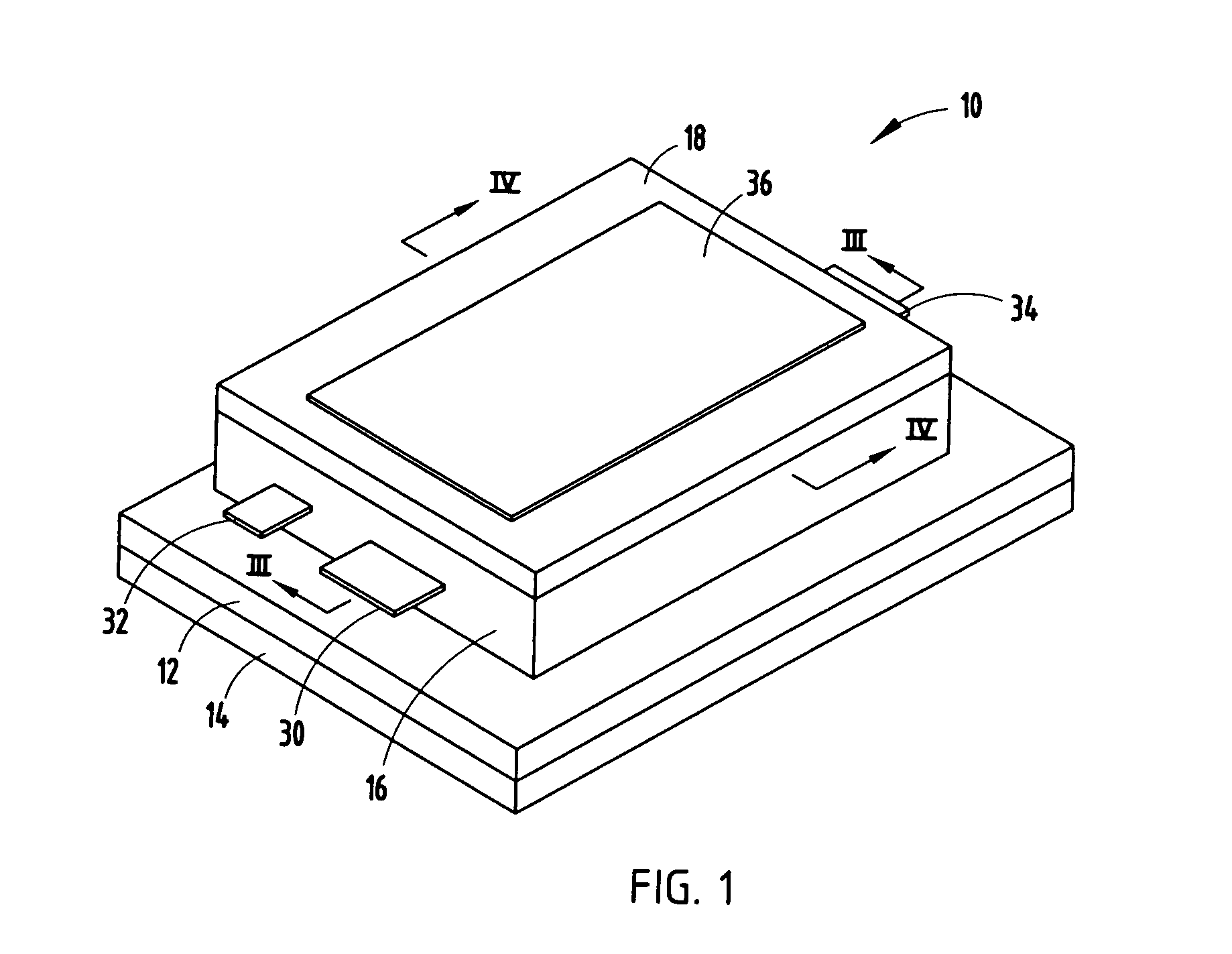
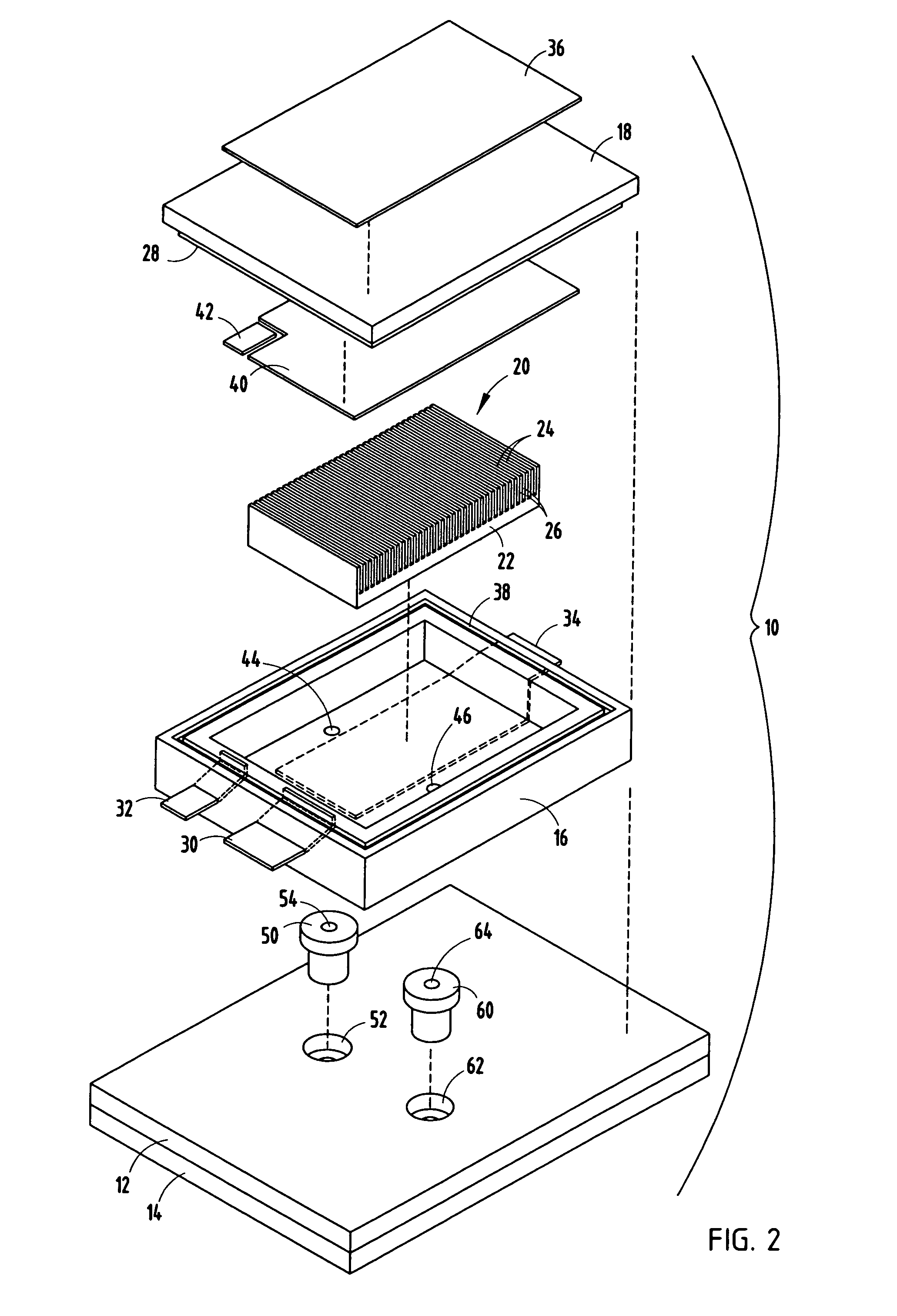
[0020]Referring to FIGS. 1-5, an electronic assembly 10 is generally illustrated according to the present invention. The electronic assembly 10 includes a surface mountable electronics substrate 12, in the form of a printed circuit board, generally containing a substrate material and electrical circuitry as is known in the art. The electronic assembly 10 also includes an electronic device 20, such as a semiconductor die / device is mounted onto the top surface of the substrate 12. The electronic assembly 10 is further configured to allow for cooling fluid, more particularly, cooling liquid, to pass through the printed circuit board 12 and in thermal communication with the electronic device 20 to conduct thermal energy always from the electronic device 20.

[0021]The substrate 12 may be in the form of a printed circuit board, according to one embodiment. The substrate 12 may include an alumina substrate, according to an exemplary embodiment. According to other embodiments, the substrate ...

third embodiment

[0031]Referring to FIG. 7, a semiconductor die / device 20 is shown in an electronic assembly 10 employing wire bond connections. In this embodiment, the semiconductor die / device 20 is positioned upside-down as compared to the embodiment disclosed in FIG. 6. A plurality of wire bonds 76 connect electrical circuit contact pads on the surface of die / device 20 to the electrical leads 72 and 74, which in turn, are connected to electrical circuitry on the printed circuit board 12. In this embodiment, the die / device 20 is positioned such that the channels 26 extend downward, and the cooling liquid flows into the sealed compartment and between the channels 26 to cool the flip chip semiconductor device 20.

fourth embodiment

[0032]Referring to FIG. 8, the electronic assembly 10 is illustrated employing an FET / IGBT die / device 20. In this embodiment, the cover 18 is electrically conductive and contacts the upper surface of the electronic device 10. The cover 18 has integrally formed electrically conductive leads 90 that extend through circuit board 12 to provide electrical circuit connections to electrical circuitry on circuit board 12 and is electrically isolated from housing 14 by isolation regions 94 on circuit board 12. The conductive cover 18 has an outward protruding portion 100 that accommodates the height of the die / device 20 relative to the housing 16. In this FET / IGBT device embodiment, the electrically conductive cover 18 and leads 90 provide the source terminal connections. The bottom surface of the electronic device 20 is in electrical contact with leads 92a and 92b, which extend down through circuit board 12 and form electrical connections to circuitry on circuit board 12 which is electrical...


PUM


Abstract

An electronic assembly is provided having a thermal cooling fluid, such as a liquid, for cooling an electronic device within a sealed compartment. The assembly includes a housing generally defining a sealed fluid compartment, an electronic device disposed within the housing and a cooling liquid for cooling the electronic device. The assembly includes inlet and outlet ports in fluid communication with the sealed fluid compartment for allowing the cooling liquid to pass through the compartment to cool the electronic device. Fluid flow channels are formed in thermal communication with the electronic device within the housing. The fluid channels include channels that allow liquid to flow in thermal communication with the electronic device to cool the device.

Description

TECHNICAL FIELD[0001]The present invention generally relates to electronics assemblies and, more particularly, relates to an electronic assembly having thermal cooling fluid for cooling the electronics.BACKGROUND OF THE INVENTION[0002]Power electronic devices employ electronics packages (devices) that generally contain electrical circuitry for conducting electrical current which, in turn, generates thermal energy (i.e., heat). Automotive high-power electronics, such as those employed in electric and hybrid-electric vehicles typically generate a significant amount of thermal energy during operation. Excessive heat build-up may cause reduced performance including electrical circuit failure. Thus, thermal energy must be dissipated and transferred away from the electronics to ensure proper operation of the package. Additionally, the power capability of the electronics package(s) and size of the electronic assembly generally depend upon the amount of heat dissipation that may be achieved...

Claims


Application Information

Patent Timeline
Patent Type & Authority Patents(United States)
IPC IPC(8): H05K7/20
CPCH01L23/053H01L23/473H01L2924/0002H01L2924/09701H01L2924/13055H01L2924/00
Inventor PEUGH, DARREL E.MYERS, BRUCE A.OBERLIN, GARY E.
Owner DELPHI TECH IP LTD
Why Eureka
Try Eureka