
Method of assigning transmission channels in a telecommunications network and user station

a transmission channel and user station technology, applied in the field of assigning transmission channels in a telecommunications network and to a user station, can solve the problem of inability to coordinate code assignment, and achieve the effect of increasing the number of simultaneous connections, ensuring the highest possible connection quality, and increasing the capacity of the telecommunications network

Active Publication Date: 2009-06-23
KAROLS DEV CO LLC
View PDF8 Cites 11 Cited by
  • Summary
  • Abstract
  • Description
  • Claims
  • Application Information

AI Technical Summary

Benefits of technology

"The present invention provides a method for assigning transmission channels in a telecommunications network and a user station for this purpose. The method optimizes the distribution of transmission channels among base stations and mobile stations, increasing the capacity of the network and the number of connections that can be set up simultaneously. The method also allows for dynamic channel assignment for existing connections, reducing interference and improving connection quality. Additionally, the method reserves specific channels for broadcasting, reducing the time and expense required for mobile stations to find the broadcast channel. The invention also suggests using scrambling codes to increase the number of transmission channels and data rate, even in uncoordinated operation of base stations."

Problems solved by technology

However, in uncoordinated operation the base stations may not be linked via a higher-order system, so that coordinated code assignment may not be possible.

Method used


Image

  • Method of assigning transmission channels in a telecommunications network and user station
  • Method of assigning transmission channels in a telecommunications network and user station
  • Method of assigning transmission channels in a telecommunications network and user station

Examples


Embodiment Construction

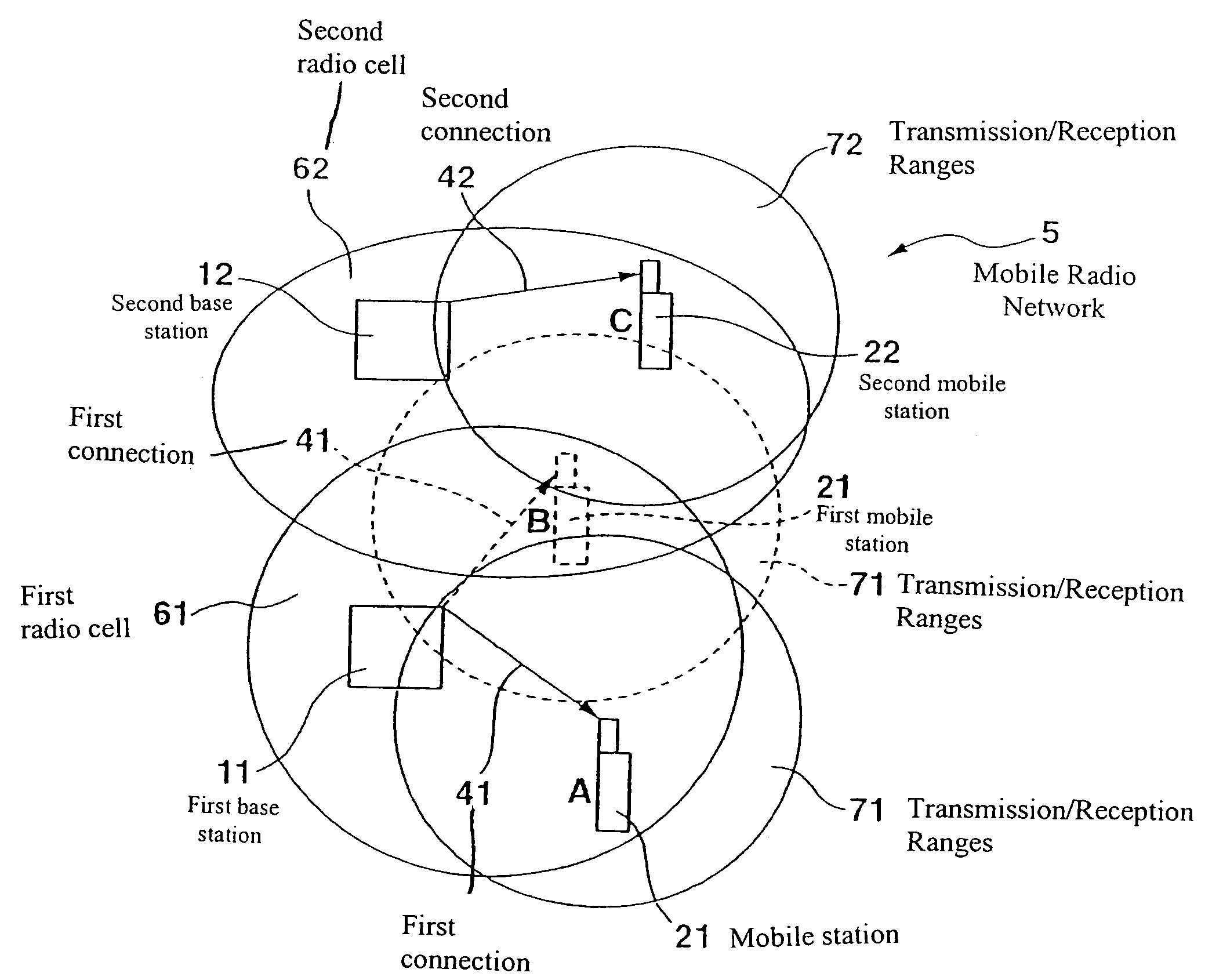
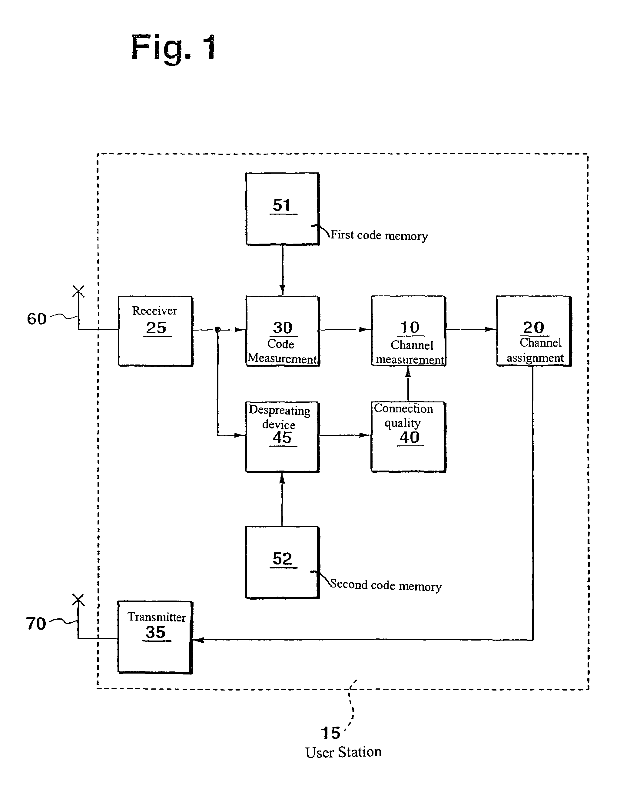
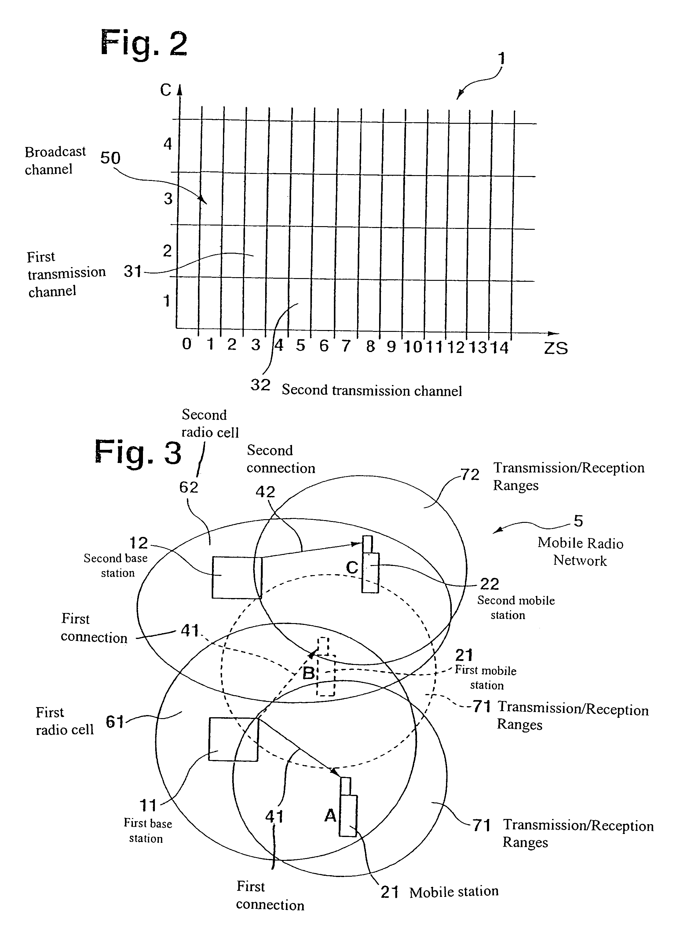
[0017]In FIG. 1, 15 identifies a user station of a telecommunications network 5. Telecommunications network 5 may be implemented, for example, as a landline network or as a mobile radio network. If telecommunications network 5 is a mobile radio network, user station 15 may include a base station 11, 12 or a mobile station 21, 22, as shown, for example, in FIG. 3. For the description to follow, it is presumed, for exemplary purposes only, that telecommunications network 5 is a mobile radio network and that user station 15 is a base station 11, 12 or a mobile station 21, 22. Mobile radio system 5 and user station 15 may be implemented, for example, according to the GSM standard (Global System for Mobile Communication), the UMTS standard (Universal Mobile Telecommunication System) or the like.

[0018]User station 15 illustrated in FIG. 1 includes a receiver 25, to which a receiving aerial 60 is connected. As shown in FIG. 1, user station 15 also includes a transmitter 35, to which a tran...


PUM


Abstract

A method of assigning transmission channels in a telecommunications network and a user station are provided, which facilitate an increase in the capacity of a telecommunications network. The telecommunications network may include multiple base stations and mobile stations, the transmission channels being provided for transmitting signals between the base stations and the mobile stations. In uncoordinated operation of the base stations, at least one of the transmission channels is assigned for transmitting signals between one of the base stations and one of the mobile stations as a function of a channel measurement, in which the transmission power on all possible transmission channels is measured, if the previously measured transmission power on this transmission channel is minimal.

Description

FIELD OF THE INVENTION[0001]The present invention relates to a method of assigning transmission channels in a telecommunications network and to a user station.BACKGROUND INFORMATION[0002]A method and a device for operation in an indoor CDMR telecommunications system are referred to in European published patent application Ser. No. 0 865 172, in which two or more wireless communications systems are operated superimposed. One of the two systems is an indoor system and the other is an outdoor system. The indoor system monitors the operation of the outdoor system and detects which part of the available radio resources are sometimes not used or are interference-free in the outdoor system. The indoor system dynamically selects an unused outdoor channel for indoor operation. The indoor radio traffic is divided into TDD time slots, which include the time slots for monitoring the existing radio connections on other outdoor channels, so that rapid changes are possible in accordance with chang...

Claims


Application Information

Patent Timeline
Patent Type & Authority Patents(United States)
IPC IPC(8): H04W72/00H04B1/707H04J3/16H04J13/16H04W16/16H04W72/54
CPCH04W16/16H04W72/085H04W24/10H04W72/0473H04W72/542
Inventor HANS, MARTINKOWALEWSKI, FRANKLAUMEN, JOSEFSCHMIDT, GUNNARLECHNER, DETLEFBAER, SIEGFRIEDBECKMANN, MARK
Owner KAROLS DEV CO LLC
Learn More