Registration correction system

a technology of registration correction and registration, applied in printing presses, office printing, printing, etc., can solve problems such as adverse effects on registration accuracy, changes in material geometry, and deviations among various imprints, and achieve the effect of minimizing spoilag

Inactive Publication Date: 2009-06-30
BOSCH REXROTH AG
View PDF9 Cites 5 Cited by
  • Summary
  • Abstract
  • Description
  • Claims
  • Application Information

AI Technical Summary

Benefits of technology

[0010]It is the object of the invention to create a registration correction system of the type defined at the outset which makes due with fewer components than in the prior art and minimizes spoilage during and after acceleration phases.
[0013]The information about the presence of an acceleration phase is available to the motion controller of the rotary printing press and can be furnished from there to the registration controller. Additional speed sensors for detecting the acceleration phase can thus be dispensed with, which leads to reduced component, assembly, and cable connection costs. This is especially true since advantageously the acceleration in all the printing groups of the printing unit is detected, and thus at the same time a plurality of speed sensors can be dispensed with. A further advantage is due to the fact that ascertaining an acceleration phase is possible even in rotary printing presses that have printing groups in which there is no space available for speed sensors.
[0015]If a more-dynamic set of correction parameters is used in the acceleration phase than at constant speed, then the registration corrector can compensate faster for registration deviations that occur during the change of speed. This can be associated with somewhat poorer print quality.
[0016]Conversely, if in the acceleration phase a less-dynamic set of correction parameters than at constant speed is used, this leads to markedly slighter adjusting motions, yet the corrector continues to be active. The control loop remains stable; registration deviations are compensated for, but the final control elements are not adjusted too far from their position at constant speed, which after the acceleration phase means that optimal operating conditions can rapidly be restored.
[0020]Because the beginning and end of the acceleration phase are reported to the registration correction device by the motion controller, no additional speed transducers are necessary, which leads to corresponding cost advantages. The corrector activity is preserved during the acceleration phase and thus minimizes spoilage. If the controlling variable is reset after the acceleration phase to the value at the beginning of the acceleration phase, or to a value derived from that, then a value of the controlling variable that is suitable for constant speeds is immediately available. This is possible since the controlling variables for different constant speeds are maximally constant, and major deviations from them occur only in acceleration phases. Resetting the controlling variable to the value before the acceleration phase thus leads much faster to a suitable value for the controlling variable at a constant speed than would be the case through the control loop alone by the correction activity of the corrector.

Problems solved by technology

The cause of deviations among the various imprints are not only the relative position of the printing groups to one another but also changes in the geometry of the material being printed.
Conversely, in both positive and negative acceleration events, the web tension varies, with an adverse effect on the registration precision.
This cannot be compensated for adequately by the correction system, which in this phase of operation leads according to rejection.
Once again, the result can be rejection.
A disadvantage of this apparatus is that to ascertain the acceleration, an acceleration detector, with at least one suitable speed indicator for detecting the web speed must be provided.
Because of the additionally required components, this not only leads to increased system costs but also, because of the necessary cable connection of the speed indicator, to increased installation costs.
Another disadvantage is that often the available space inside the printing unit does not make it possible to mount the speed indicator in a suitable position.
This leads to an increased registration deviation during the acceleration phase and thus to increased rejection.

Method used


Image

  • Registration correction system
  • Registration correction system
  • Registration correction system

Examples


Embodiment Construction

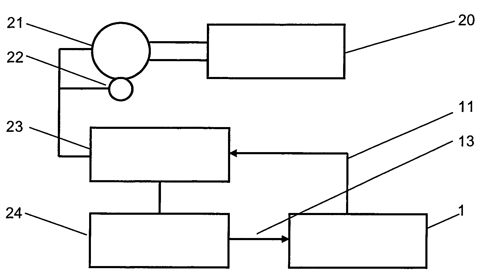
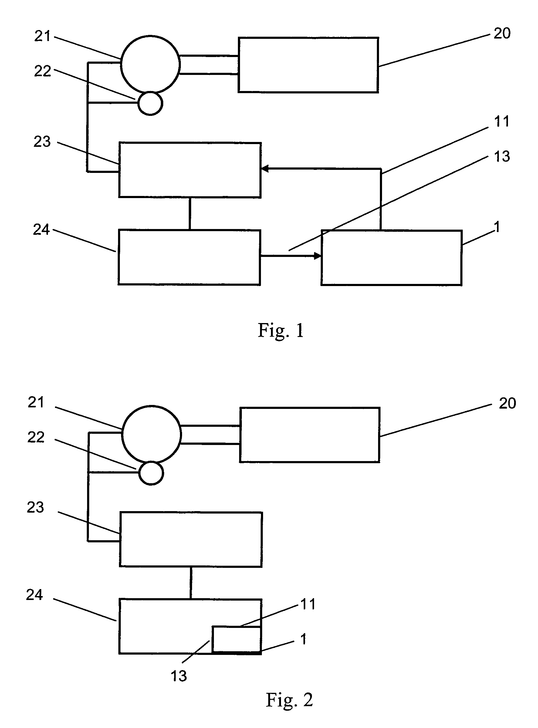
[0027]FIG. 1 shows a registration correction system 1 with a motion controller 24 for a print roller 20 with an external registration correction system 1. The registration correction 1 acts via a controlling variable 11 on a switchover device 23, which supplies a drive motor 21 that in turn moves the print roller 20. The motion of the drive motor 21 is recorded by a rotary angle encoder 22 and is carried onward via the switchover device 23 to the motion controller 24. The registration correction system 1 receives an acceleration signal 13 from the motion controller 24. The acceleration signal 13 may be transmitted in binary form (for instance as a “set-point speed value attained” signal) or as an analog signal that represents the actual value of the acceleration.

[0028]FIG. 2 shows a registration correction system 1 that is integrated with the motion controller 24. Both the acceleration signal 13 and the controlling variable 11 occur only within the motion controller 24, making compl...


PUM


Abstract

In a method for registration correction for a multicolor rotary printing press in an acceleration phase, having at least one registration correction device with correction parameters for operation of constant speed, and having a motion controller for controlling the print roller speed, if the registration correction device is acted upon in the acceleration phase by at least one fixed set of the correction parameters, which differs from the correction parameters at constant speed, and / or in the acceleration phase, a correction profile that is modified compared to constant speed is used, and / or information about the presence of the acceleration phase is supplied by the motion controller to the registration correction device, then it can be attained that in both methods, during the acceleration phase, the corrector continues to remain active, and even in this phase, it compensates for registration deviations. By the set of correction parameters that is modified compared to constant speed, or correction values, the registration corrector can be optimally adapted to requirements during the acceleration phase, and thus minimal registration offset can be attained. After the acceleration phase, the correction parameters or correction values are reset to the values before the acceleration phase for constant speed.

Description

CROSS-REFERENCE TO A RELATED APPLICATION[0001]The invention described and claimed hereinbelow is also described in German Patent Application DE 10 2005 033 585.3-27 filed on Jul. 19, 2005. This German Patent Application, whose subject matter is incorporated here by reference, provides the basis for a claim of priority of invention under 35 U.S.C. 119(a)-(d).BACKGROUND OF THE INVENTION[0002]The invention relates to a method for registration correction for a multicolor rotary printing press in an acceleration phase, having at least one registration correction device with correction parameters for operation of constant speed, and having a motion controller for controlling the print roller speed.[0003]In multicolor printing in rotary printing presses, the application of the individual color separations, especially for cyan, magenta, yellow, and black, is done in successive printing groups. The material to be printed is furnished in rolls and is guided in endless fashion through the prin...

Claims


Application Information

Patent Timeline
Patent Type & Authority Patents(United States)
IPC IPC(8): B41F13/24
CPCB41F13/025B41F33/0009
Inventor DOERES, HANS-JUERGENSCHULTZE, STEPHAN
Owner BOSCH REXROTH AG
Why Eureka
Try Eureka