Generator and method for generating electricity from subsurface currents

a technology of subsurface current and generator, which is applied in the direction of electric generator control, machines/engines, mechanical equipment, etc., can solve the problems of confined mechanical devices that will eventually undergo fatigue and break, and the machine at these locations requires huge capital investments,

Inactive Publication Date: 2009-06-30
GREGORY CARAGINE
View PDF64 Cites 18 Cited by
  • Summary
  • Abstract
  • Description
  • Claims
  • Application Information

AI Technical Summary

Benefits of technology

[0018]In one embodiment this series of electrical coils forms an electrical generator located in one column of a rectangular support frame that also supports a number of identical parallel generators located in adjacent columns. This frame with its multiple generators is rotatably mounted on a vertical beam together with, for example, two more identical frames each having multiple generators.

Problems solved by technology

Machinery at these locations requires huge capital investments, dam constructions, and other unsightly changes to the natural beauty of the sea.
They are very confined mechanical devices that will eventually undergo fatigue and break.
These are also wave machines that are positioned out to sea and do not take advantage of the subsurface back and forth motion of water.

Method used


Image

  • Generator and method for generating electricity from subsurface currents
  • Generator and method for generating electricity from subsurface currents
  • Generator and method for generating electricity from subsurface currents

Examples


Embodiment Construction

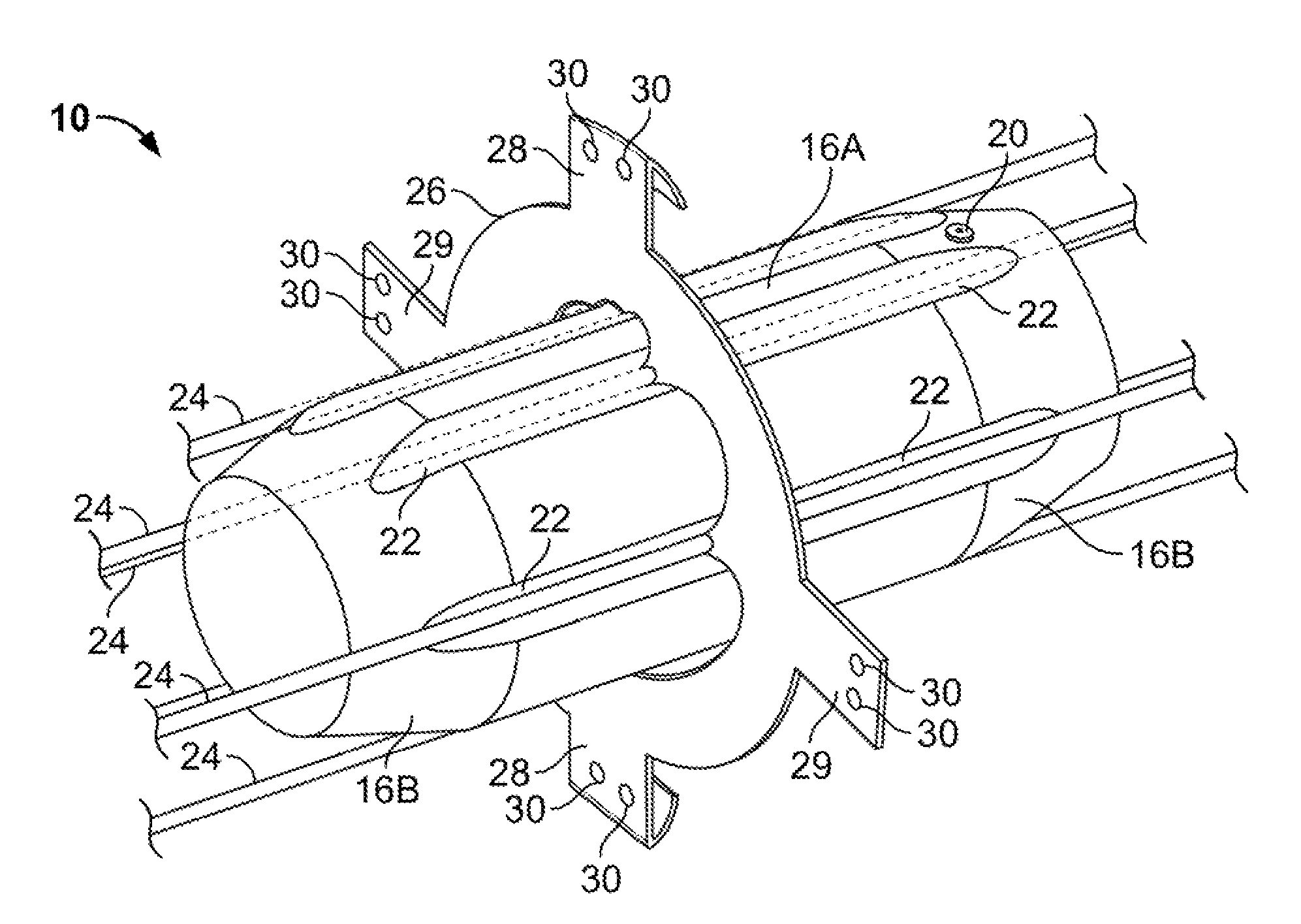
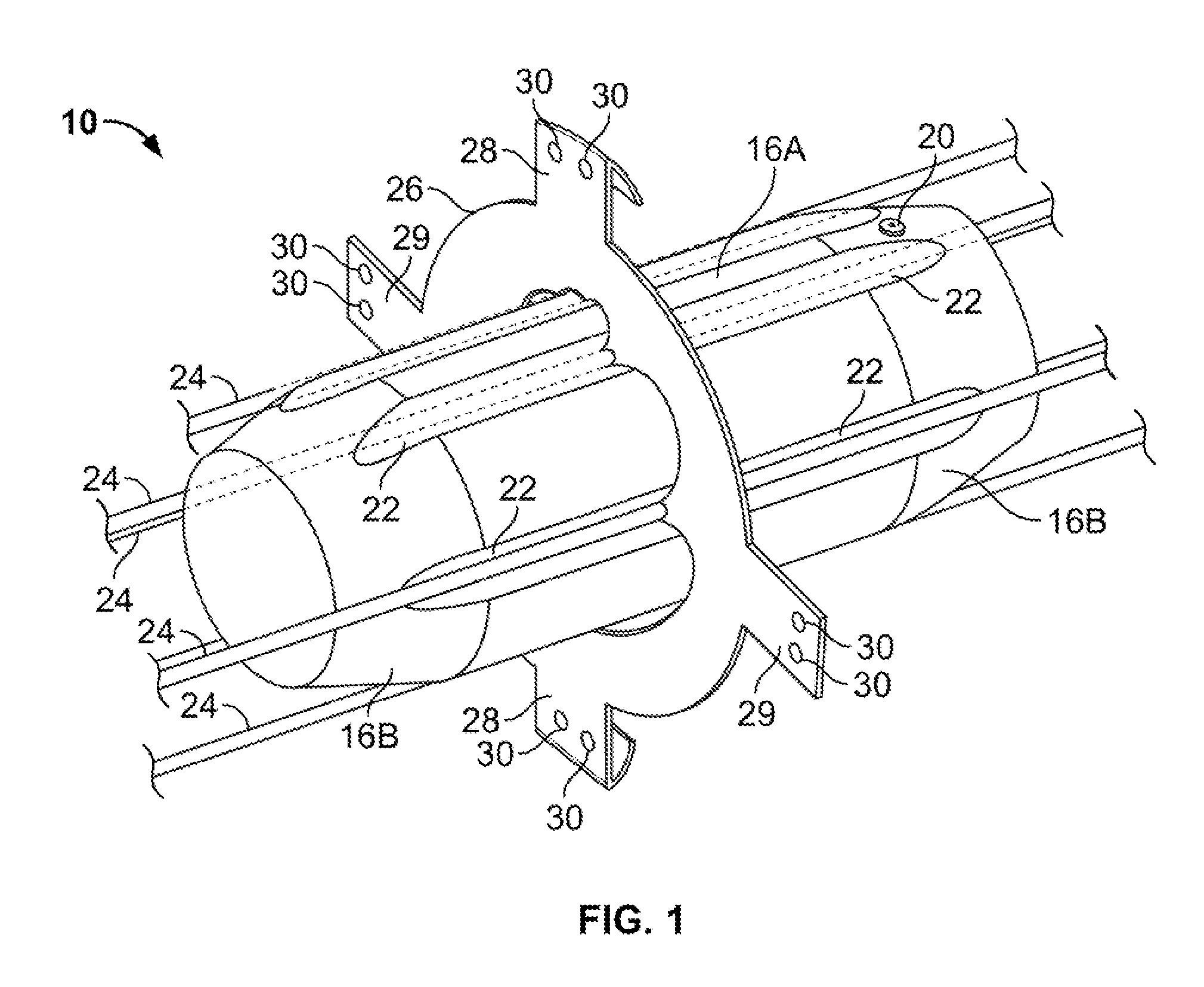
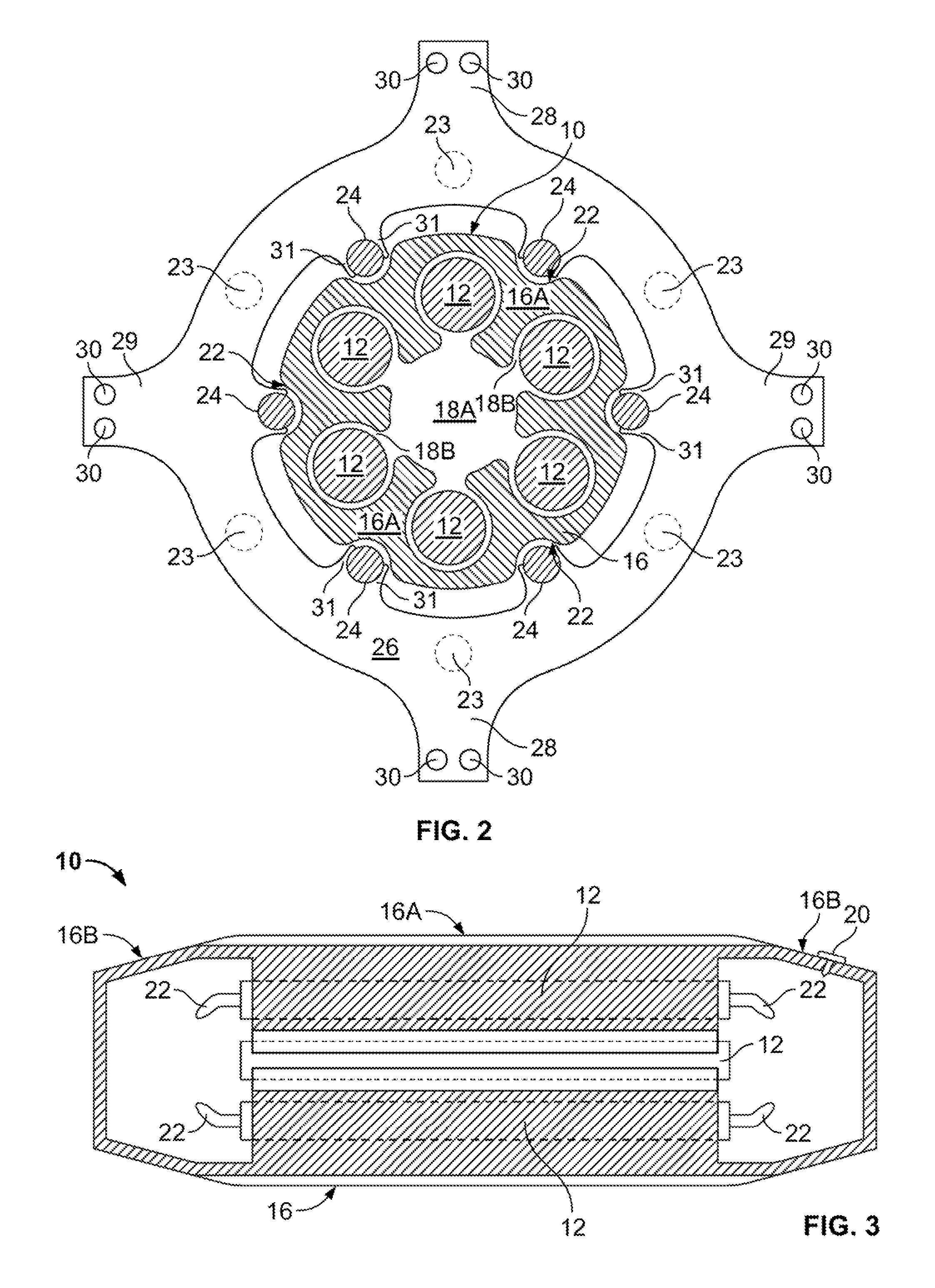
[0030]Referring to FIGS. 1-3, shuffle 10 has a generally cylindrical midsection 16A between tapered frustoconical ends 16B (collectively referred to as case 16). Cylindrical midsection 16A has a central chamber 18A with six cylindrical cavities 18B circumferentially and equiangularly spaced about the longitudinal axis of shuttle 10.

[0031]Cylindrical cavities 18B each hold a cylindrical magnetic element 12. Elements 12 are rods made of rare earth magnets (or other magnetic material) oriented with all their north-south poles oriented in the same way. Magnetic elements 12 are in the illustrated embodiment approximately 4 inches (10 cm) in diameter and 3.5 feet (1 m) in length. In some embodiments, magnetic elements 12 may have a different size and shape, such as triangular or rectangular prisms with a different overall size. Consequently, cavities 18B may have alternative complementary shapes and sizes to accommodate different magnetic elements.

[0032]The outer surface of midsection 16A...


PUM


Abstract

A generator can convert the energy from subsurface currents or undertow into electricity. The generator has a submergible electrical coil adapted to allow water propelled by subsurface currents to enter and flow axially through the coil. The electrical coil is supported above a sea floor in substantial alignment with the subsurface currents. A magnetic shuttle is mounted to longitudinally reciprocate in the coil, driven by water flowing through the coil. Additionally, a plurality of electrical coils can be submerged above a sea floor. Magnetic shuttles are placed separately into a corresponding one of the coils to longitudinally reciprocate, driven by water flowing through the coils.

Description

BACKGROUND OF THE INVENTION[0001]1. Field of the Invention[0002]The present invention relates to converting subsurface currents into electricity and, in particular, to conversion using a coil and magnetic element.[0003]2. Description of Related Art[0004]It is the experience of many who have gone to the seashore and stood in the water perhaps 10-50 yards from the water's edge that there is an extremely powerful alternating inflow and outflow of water 1-5 feet beneath the surface. This ebb and flow of water occurs about 4 times per minute and has tremendous kinetic energy.[0005]In the past 50 years a number of different devices have been designed to try to harness the kinetic energy of moving ocean water in usable ways.Tidal[0006]Some energy conversion devices have relied on positioning at flood plains, such as those at the Bay of Fundy on the eastern coast of Canada or St. Malo on the Brittany Coast in France (across the La Rance Estuary). In these locations, there is a powerful infl...

Claims


Application Information

Patent Timeline
Patent Type & Authority Patents(United States)
IPC IPC(8): F03B13/10F03B13/12
CPCF03B17/00F03B17/06Y02E10/28Y02E10/30Y02E10/20
Inventor CARAGINE, PAUL
Owner GREGORY CARAGINE
Why Eureka
Try Eureka