
Tightening tool and tightening tool management system

a technology of tool management system and tightening tool, which is applied in the direction of force/torque/work measurement apparatus, instruments, nuclear elements, etc., can solve the problems of only becoming known, unable to determine that the tightening torque has deviated from the predetermined, and unable to tighten the fastener smoothly

Inactive Publication Date: 2009-07-07
MAKITA CORP
View PDF30 Cites 31 Cited by
  • Summary
  • Abstract
  • Description
  • Claims
  • Application Information

AI Technical Summary

Benefits of technology

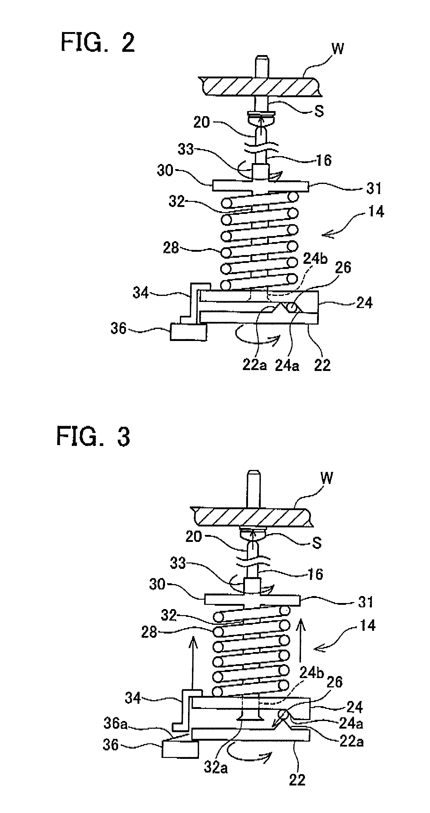
The present invention provides a tightening tool with a clutch for shutting off torque transmission, which can self-diagnose the tightening torque of a fastener at a reasonable cost without the use of expensive means such as a torque sensor. The tightening tool includes a motor, a main shaft which engages with the fastener, and a clutch disposed between the motor and the main shaft. The clutch rotates the main shaft by transmitting torque from the motor to the main shaft when the load acting on the main shaft is less than a predetermined value, and shuts off torque transmission from the motor to the main shaft when the load acting on the main shaft reaches or exceeds the predetermined value. The clutch includes a mechanical clutch mechanism and a current detecting means for detecting the current flowing to the motor, which can determine the tightening torque of the fastener by learning the value of the current at the time of torque transmission shut-off. The tightening tool may also include a clutch activation detecting means for detecting when the clutch has shut off torque transmission.

Problems solved by technology

Therefore, the load applied by the clutch (i.e. the load when torque transmission is shut off) decreases over time due to wear of the clutch members, causing variation in the tightening torque of the fastener.
However, with this method, if the tightening torque deviates from the predetermined value during the operation for one reason or another (for example, due to clutch damage), it is impossible to determine that the tightening torque has deviated from the predetermined value at that point in time, and the deviation only becomes known from the measurement that is performed at the end of the operation period.
However, a torque sensor is expensive and leads to an increase in cost.

Method used


Image

  • Tightening tool and tightening tool management system
  • Tightening tool and tightening tool management system
  • Tightening tool and tightening tool management system

Examples


Embodiment Construction

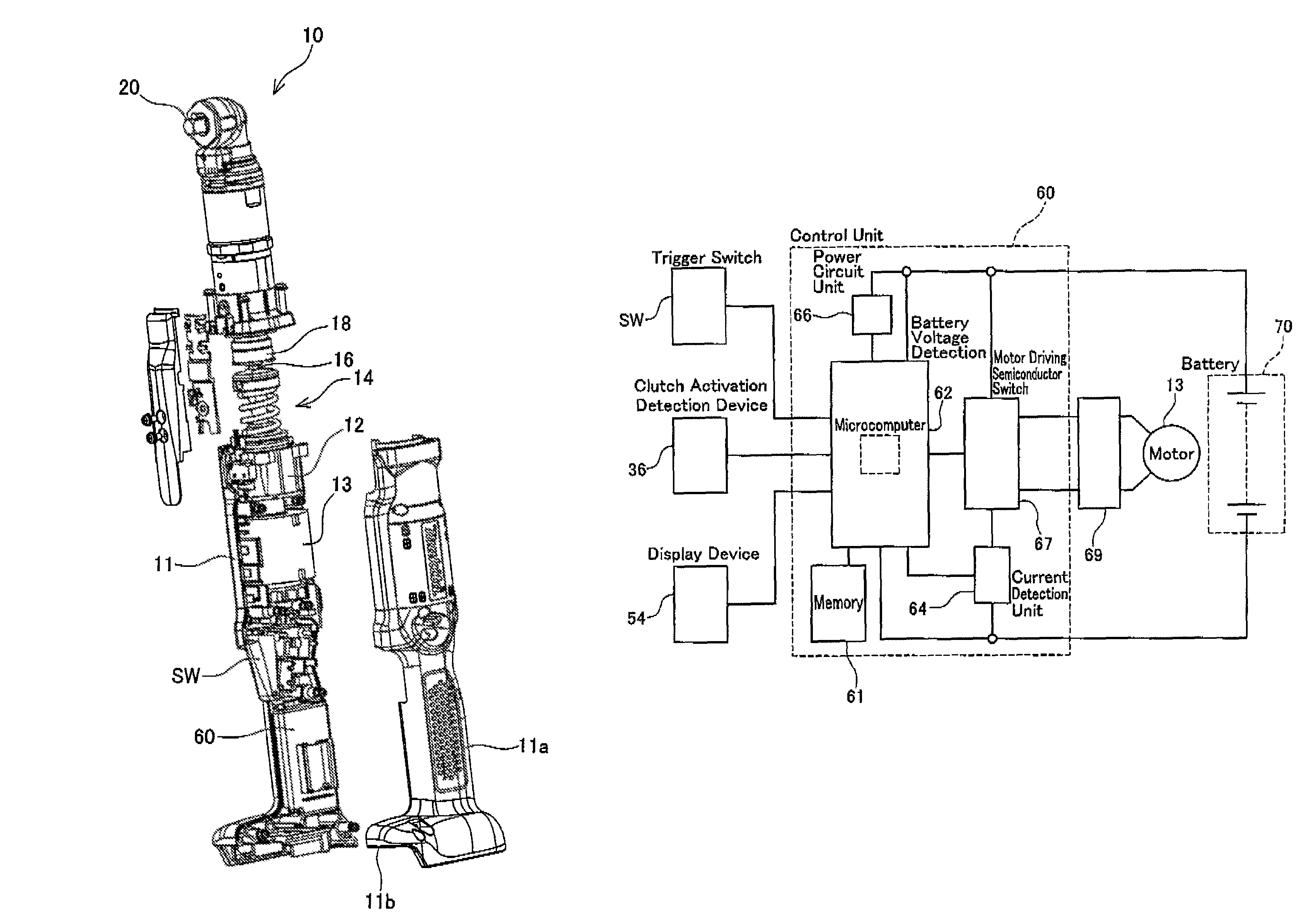
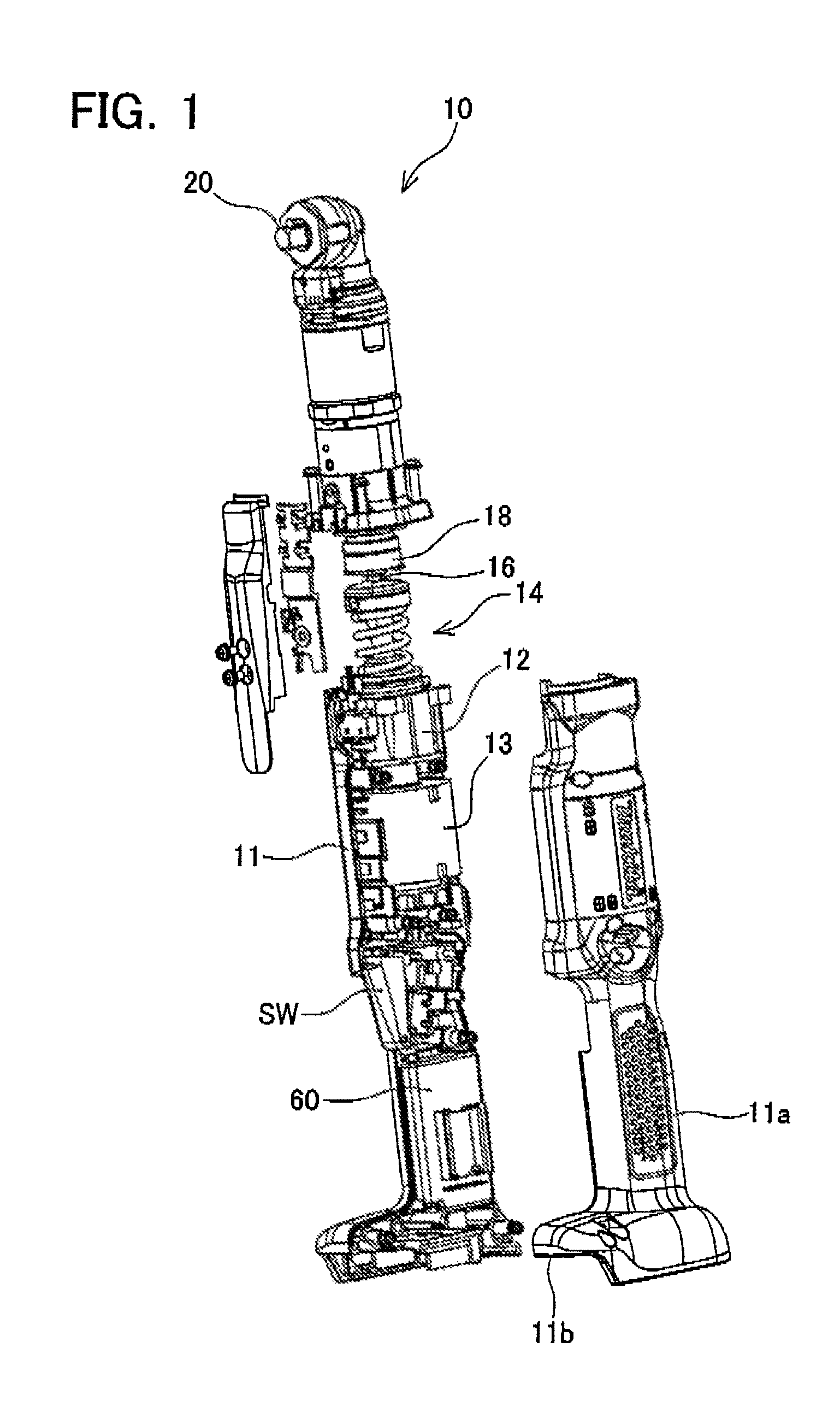
[0038]A tightening tool according to an embodiment of the present invention will be described below. FIG. 1 is an exploded perspective view of the tightening tool. A tightening tool 10 shown in FIG. 1 includes a motor 13 serving as a drive source, which is housed in and fixed to a housing 11. The motor 13 is a brushless DC motor, and the mechanical inertial force (inertia) of the rotor is set to be small. A planetary gear mechanism 12 is connected to an output shaft of the motor 13. A rotary shaft 16 is connected to an output shaft of the planetary gear mechanism 12 via a clutch mechanism 14. The rotary shaft 16 is supported by a bearing device 18, and a bevel gear (not shown) is fixed to the tip end thereof. The bevel gear fixed to the rotary shaft 16 engages a bevel gear (not shown) fixed to a base end portion of a spindle 20. A socket (not shown) which engages with a head portion of a fastener (a bolt, nut, or screw etc.) is attached to the other end of the spindle 20.

[0039]In th...


PUM


Abstract

A fastening tool with a clutch for shutting off transmission of torque, capable of self-diagnosing fastening torque of a screw or the like at low cost without using expensive elements such as a torque sensor, etc. A fastening tool (10) has a motor (13), a main shaft (20) engaging with a screw or the like, and a clutch (14) interposed between the motor (13) and the main shaft (20). The clutch (14) transmits torque from the motor (13) to the main shaft (20) when a load acting on the main shaft (20) is less than a predetermined value, and shuts off torque transmission from the motor (13) to the main shaft (20) when a load acting on the main shaft (20) is equal to or greater than the predetermined value. The fastening tool (10) further has a control unit (60) for controlling the motor (13). The control unit (60) monitors a current flowing to the motor (13) and determines whether fastening torque is normal or not based on a motor current when transmission of torque from the motor (13) to the main shaft (20) is shut off.

Description

TECHNICAL FIELD[0001]The present invention relates to a tightening tool for tightening a fastener (for example, a bolt, a nut, a screw, and so on), and more particularly to a tightening tool having a clutch which shuts off torque transmission to the fastener when a tightening torque reaches a preset value.BACKGROUND ART[0002]Japanese Patent Application Publication No. 11-179673 discloses a tightening tool for shutting off torque transmission to a fastener when the tightening torque of the fastener reaches a predetermined value. In this tightening tool, the rotary torque of a motor is transmitted to a main shaft via a clutch, and the fastener is tightened by rotating the main shaft. The clutch used in this type of tightening tool comprises a pair of mutually opposed clutch members and biasing means (e.g., a spring) for pressing one of the clutch members toward the other, for example. When the tightening torque of the fastener (i.e. the load acting on the main shaft) is lower than the...

Claims


Application Information

Patent Timeline
Patent Type & Authority Patents(United States)
IPC IPC(8): B25B23/14B25B23/147
CPCB25B23/147B25B23/14B25B23/141
Inventor MATSUNAGA, YUTAKA
Owner MAKITA CORP
Learn More