Method and apparatus for collating nails

a technology of collating nails and nails, applied in the field of collating nails, can solve the problems of difficulty in being able to supply and arrange a plurality of round headed nails, and achieve the effect of increasing speed

Inactive Publication Date: 2009-07-07
KIM CHI HYUN
View PDF12 Cites 13 Cited by
  • Summary
  • Abstract
  • Description
  • Claims
  • Application Information

AI Technical Summary

Benefits of technology

[0006]The present invention provides an apparatus for rapidly indexing and feeding a plurality of nails in a spaced horizontal relationship to a collator for subsequent collating into a strip of nails secured to a substrate or supporting web at an increased speed than heretofore believed possible with existing collators for round headed nails.
[0009]A further feature of the present invention is to provide such an apparatus which uses a plurality of L-shaped segments which are attached to a moving belt of the conveyor, each of which is formed with a series of spaced notches or grooves which align with the notches or grooves of adjacent segments for receiving the nails in a parallel relationship, wherein the shanks of the nails are angled slightly with respect to the longitudinal axis of the conveyor in order to assist in providing the increased speed of the indexing and feed wheel and proper angular orientation of the nails for subsequent collation.

Problems solved by technology

It has been found difficult to be able to supply and arrange a plurality of round headed nails by the use of such mechanism with sufficient speed to be utilized with a nail collator due to the spacing required between the round headed nails and movement thereof into the spaced parallel relationship required for subsequent bonding to a supporting substrate or web.

Method used


Image

  • Method and apparatus for collating nails
  • Method and apparatus for collating nails
  • Method and apparatus for collating nails

Examples


Embodiment Construction

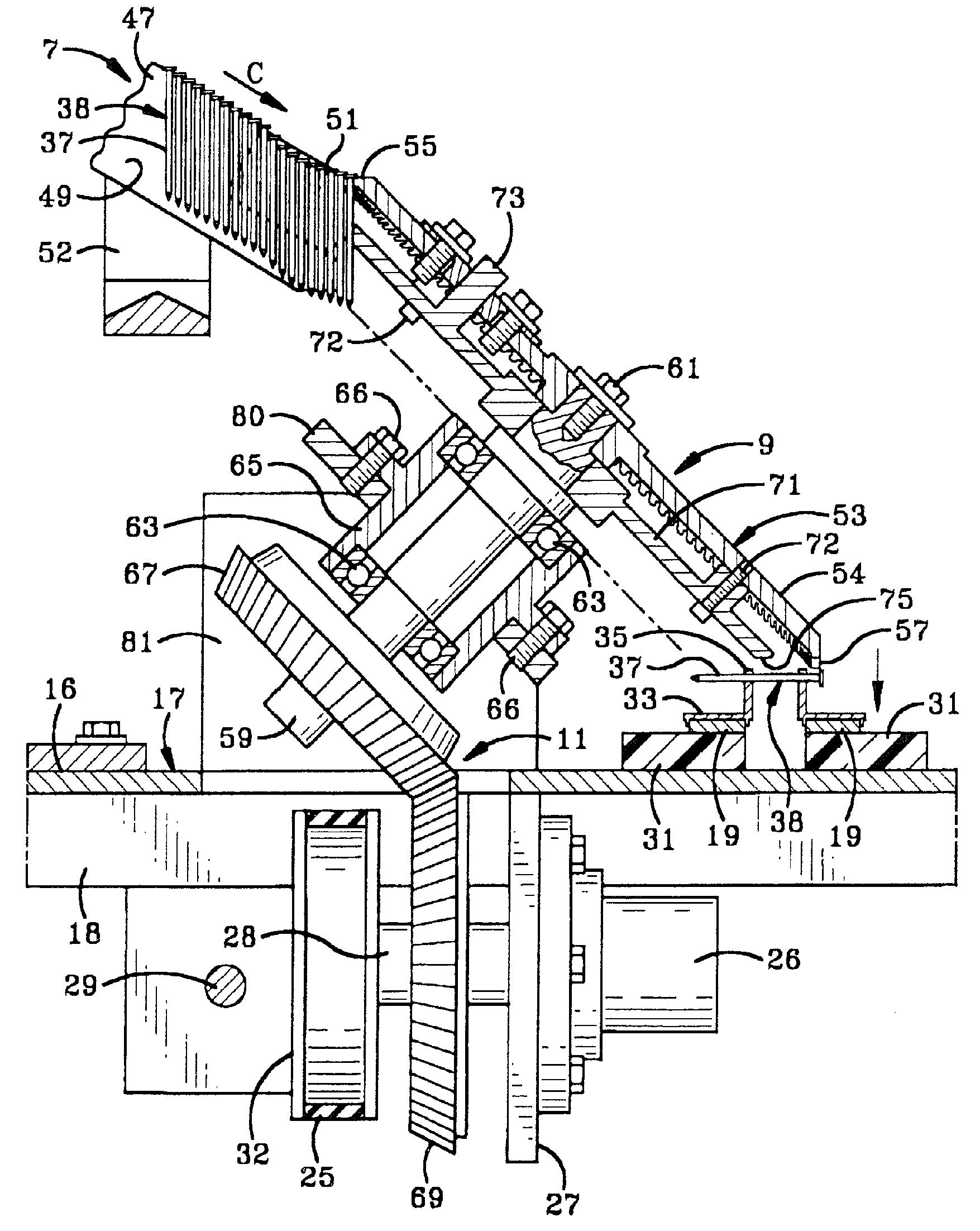
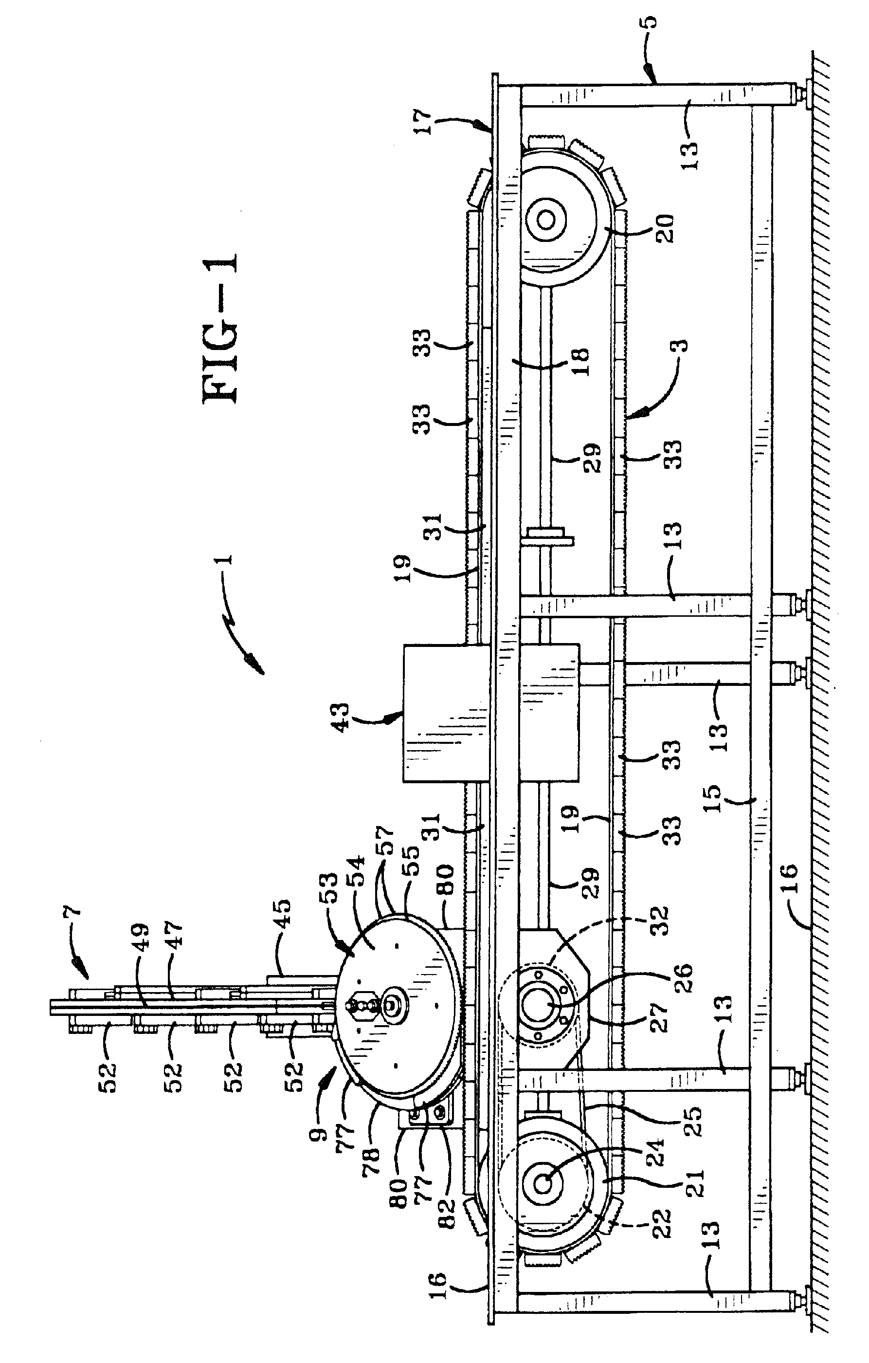
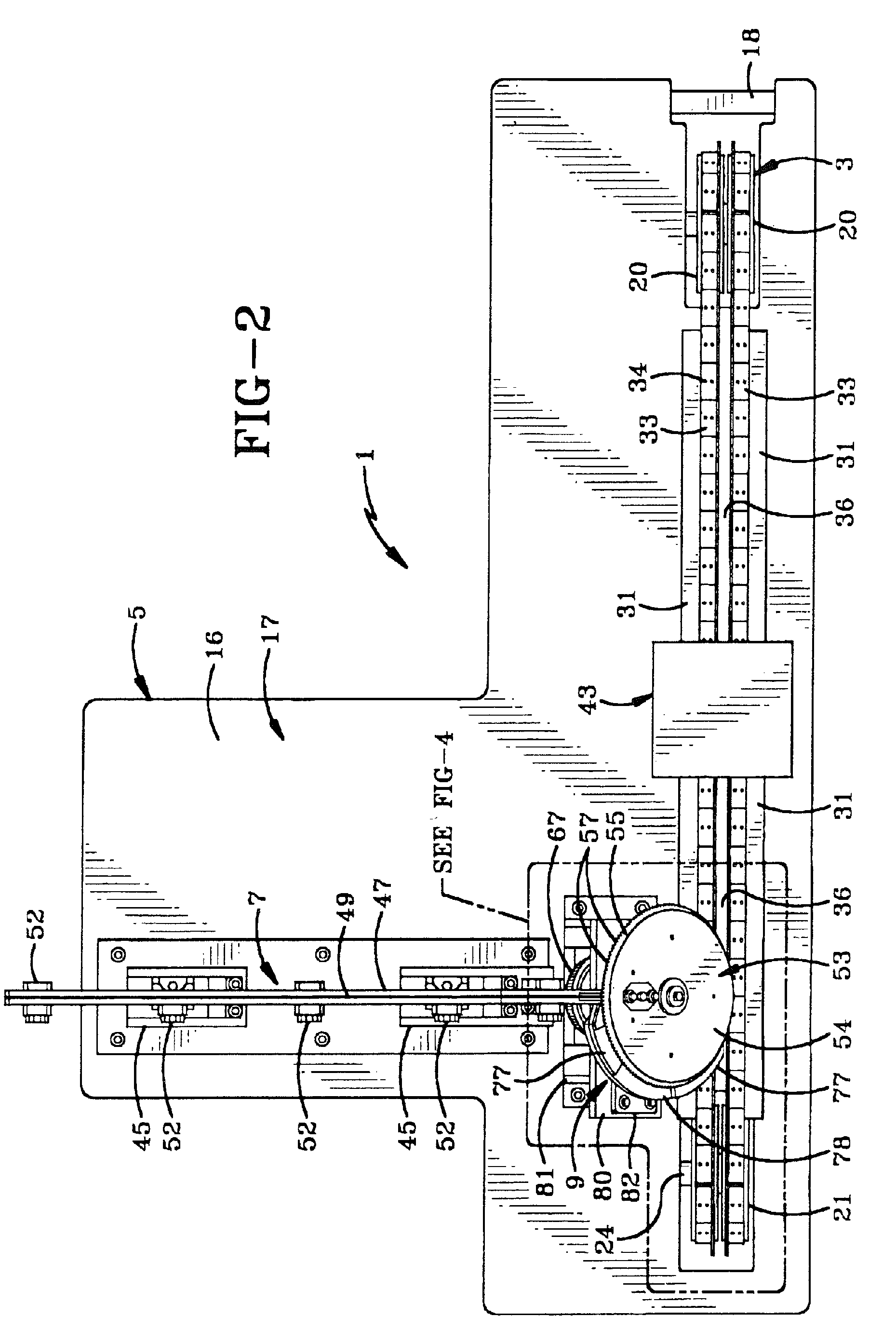
[0028]FIG. 1 is a side elevational view of the improved apparatus of the present invention and is indicated generally at 1. Apparatus 1 includes a conveyor indicated generally at 3, which is mounted on a supporting structure indicated generally at 5. Apparatus 1 further includes a nail feed mechanism indicated generally at 7, which supplies a plurality of nails to a nail indexing and feed wheel indicated generally at 9. Feed mechanism 9 is drivingly connected in synchronization with conveyor 3 by a gear train 11. Support structure 5 includes a plurality of vertical and horizontal frame members 13 and 15 respectively, and is adapted to rest upon a supporting surface 16.

[0029]Conveyor 3 is mounted in a horizontal planar table top 17, which is supported on an upper horizontal frame member 18. Conveyor 3 may have various configurations, with a preferred type being shown in the drawings. Conveyor 3 includes a pair of spaced continuous belts 19 which extend about a pair of drive wheels 20...


PUM


Abstract

An apparatus and method for collating nails wherein round head nails are fed by gravity along an inclined rail to a periphery of a rotating indexing and feed wheel. The nails are deposited into circumferentially spaced grooves formed in the periphery of the feed wheel in a vertical orientation. The feed wheel is inclined at an angle of approximately 45° and upon 180° rotation of the feed wheel the nails assume a horizontal orientation. A conveyor has a plurality of spaced segments attached to a pair of moving belts. Each segment is formed with spaced notches for receiving the nails in a horizontal spaced relationship from the feed wheel and then transporting the horizontally spaced nails to a collator for forming into a continuous strip. Rotation of the feed wheel is synchronized with movement of the conveyor by a motor, a gear train and drive shafts extending between the feed wheel and conveyor.

Description

BACKGROUND OF THE INVENTION[0001]1. Technical Field[0002]The invention relates to collating nails, and in particular to a method for collating full round head nails with increased speed by use of a gear driven inclined feed wheel synchronized with a moving conveyor wherein the feed wheel receives the nails in a vertical orientation and delivers them onto the conveyor in a horizontal orientation.[0003]2. Background Information[0004]Collated nails are used in many industrial nailing applications wherein the nails are secured in a continuous web or belt-like condition for automatically feeding the nails into a power driven nailer. These nails are secured in the web by various mechanisms such as welding of a small wire to the spaced nails, connection by hot melt adhesive strips or other substrates for holding the nails in a secure continuously spaced condition along the substrate or feed web.[0005]Various mechanisms are used to arrange the nails in a spaced parallel relationship for sub...

Claims


Application Information

Patent Timeline
Patent Type & Authority Patents(United States)
IPC IPC(8): B65B19/34
CPCB21G3/00B65B35/08F16B15/08B65G29/02B65G47/848B65B35/56
Inventor KIM, CHI HYUN
Owner KIM CHI HYUN
Why Eureka
Try Eureka