Manual wheelchair drive system

a drive system and manual technology, applied in the direction of wheelchair/patient transportation, transportation and packaging, cycles, etc., can solve the problems of inability to provide a silent means of propulsion in the prior ar

Active Publication Date: 2009-07-07
MITTELSTAEDT MARK
View PDF12 Cites 5 Cited by
  • Summary
  • Abstract
  • Description
  • Claims
  • Application Information

AI Technical Summary

Benefits of technology

[0008]When the drive rod is passed through the extent of the drive lever handle and thence through an aperture on the drive lever mounting pin, and the axle has rotated such that an aperture in the axle, perpendicular to its axis of rotation, is now beneath the aperture in the drive lever mounting pin, the drive rod slides into the aperture in the drive axle for drive engagement. Once the drive rod has been engaged, forward pressure on the drive handle(s) provides silent rotational motion of the axle, thereby propelling the chair as a result of the pressure applied by the drive lugs against the spokes of the wheel. The distal tip of the drive rod is rounded to facilitate its' passage into the aperture in the drive axle. In other embodiments, several holes are drilled through the axle perpendicular to its axis of rotation, to minimize the amount of rotation of the axle required for drive engagement.
[0010]A drive axle extends through the drive lever mounting pin, and then through a one-way bearing mounted in a bearing housing. The axle is coupled to the bearing by an attachment means. The bearing housing and lever mounting pin are retained on the axle by retaining rings. The housing is attached to the spokes of the existing wheelchair wheel by an attachment means, such that the drive axle's axis of rotation is coaxial with the wheelchair drive wheel's axis of rotation. The outer diameter of the drive axle is firmly coupled to the inner diameter of the one-way bearing by an integrated coupling means. The one-way bearing provides no resistance when the said drive axle is rotated in the reverse direction. Therefore, the lever can be easily returned to the point at which forward pressure can then be resumed to drive the chair forward. In the preferred embodiment, one of these mechanisms is mounted on each drive wheel of a wheelchair.
[0013]As an associated, dedicated, safety factor, brake shoes are mounted to each drive lever such that, depending on the embodiment, they contact either the outer surface of the wheelchair rim, or the hand-ring, when the user flexes the drive handle towards the user, thereby applying frictional contact between the brake shoe and one of the above surfaces. Flexing one lever towards the user, thereby applying frictional braking to one of the surfaces, provides an element of steering control to the wheelchair. The chair can be easily turned, either at rest or while in motion, by braking with one lever and applying forward power with the other. When one drive lever is disengaged by retraction of the axle rod, and the lever handle is flexed so as to provide friction between the brake shoe and the wheel or hand-ring, and then rotated to provide reverse travel, and the opposite lever is used to provide forward motion, the chair can be pivoted in place, so the user can turn around in a very small space, like an elevator. If both drive rods are disengaged, frictional contact and rearward rotation of both handles can then be utilized as a means of driving the chair reverse.
[0015]The mechanical advantage provided by the drive system lever, coupled with the power transmission resulting from mounting a drive axle coaxial within the hub of an existing wheel, utilizing a one way bearing clutch to provide a simple—and silent—mechanism for returning the lever to its drive position, allows wheelchair users to propel a wheelchair using the large muscles in their upper bodies, in a relaxed and upright position, while maintaining a continuous grip on the handle for control and braking. Thus, it will be appreciated that the invention provides a new and improved manual wheelchair driving system.

Problems solved by technology

The fundamental physical requirements of an individual utilizing a manual wheelchair are inherently contrary to abilities and limitations of the impaired because in general, and by design, manually powered wheelchairs require the user to grasp a circular hand-ring that is attached to the wheelchair drive wheel.
The prior art lacks the ability to provide a silent means of propulsion, so the user of a lever-driven wheelchair is not accompanied by noise whenever the user moves the chair.
Therefore, traveling short distances require the handle to travel distances out of proportion to the desired distance of travel, making small position adjustments difficult when using a drive system comprising a ratchet wrench.
Another problem with Oxford's approach is the difficulty in using the levers on either side of the chair independently.
If they are loose enough so they can easily slide past each other and allow independent use of the levers, there will be more play in the mechanism, which will make the chair noisy, and less efficient to operate.
Another, more glaring problem with Oxford's approach is that the U-shaped member has to be removed each time a user needs to enter or exit the chair, then re-assembled when the user needs to re-enter the chair.
The prior art fails to provide a system that is easy to use and easy to access, so a user can sit down in the chair and immediately start moving the chair by pressing on the lever handles, with no adjustments required, no mechanisms to move out of the way, no switches to locate to place the drive system in neutral, and no gears, cables, sprockets, or any other exposed hardware to present a physical hazard to the impaired.

Method used


Image

  • Manual wheelchair drive system
  • Manual wheelchair drive system
  • Manual wheelchair drive system

Examples


Embodiment Construction

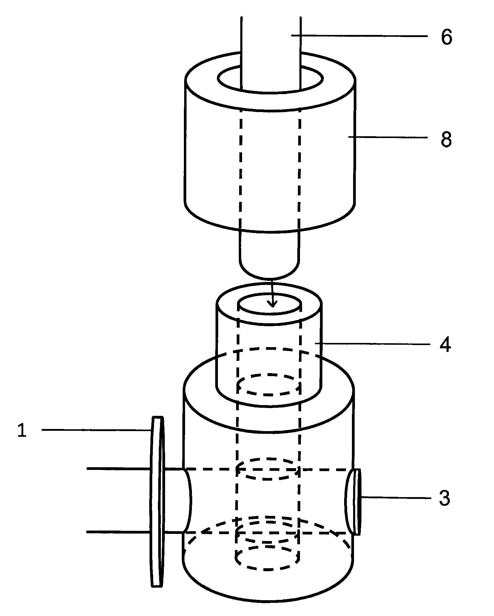
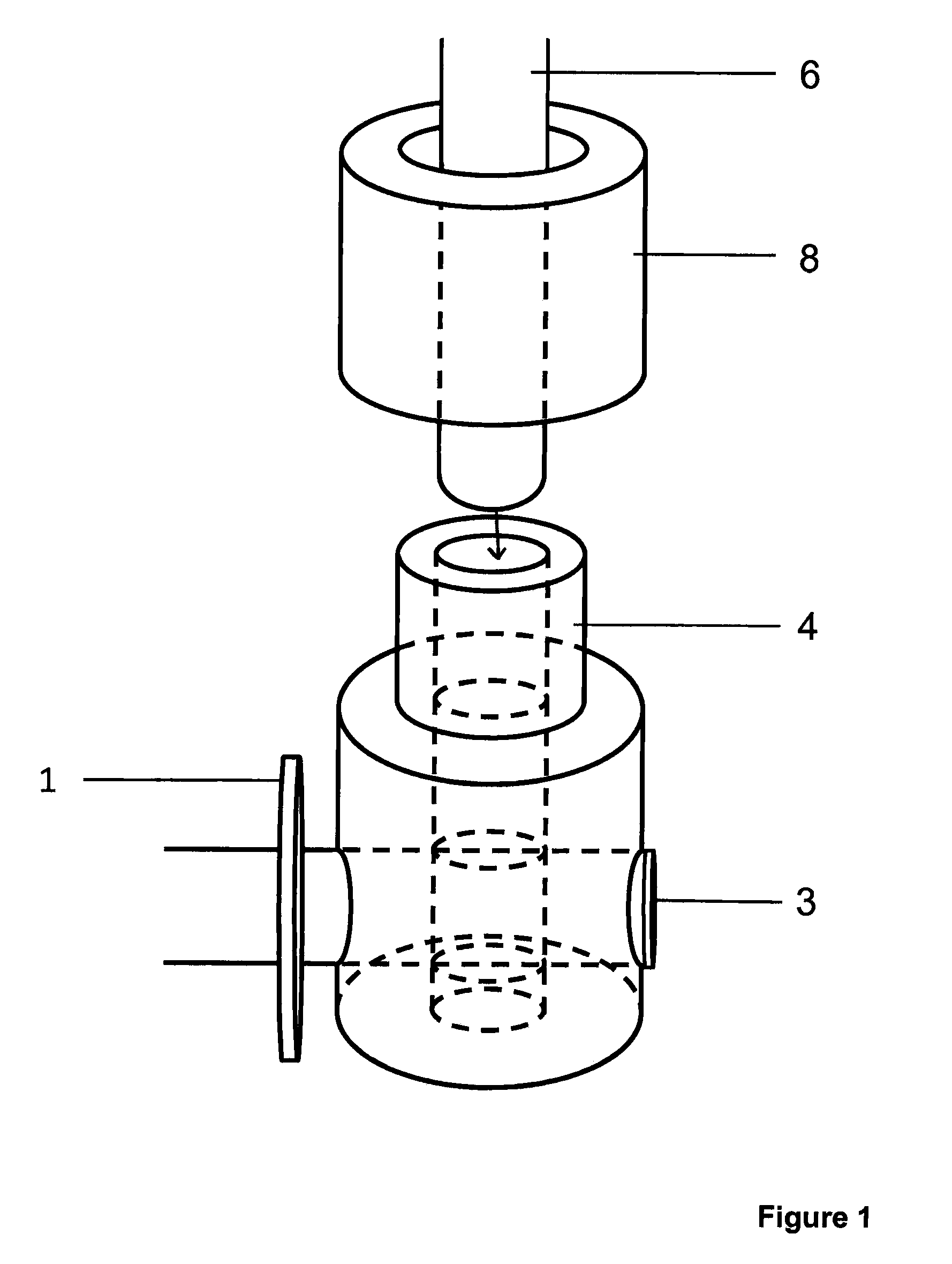
[0026]FIG. 1 shows a perspective cross section of a drive axle 3 extending through an aperture of drive lever mounting pin 4, and then through the center of one-way bearing 1. Apertures for drive rod 6 in drive lever mounting pin 4 and axle 3 can be seen; dotted lines describe both apertures. The distal tips of drive rod 6 and drive lever 8 can be seen above drive lever mounting pin 4. The distal tip of the tubing comprising drive lever 8 is pressed down to the shoulder of drive lever mounting pin 4, and then permanently attached via an attachment means upon assembly. The driver lever 8, or handle, is in one embodiment as a metal tubing.

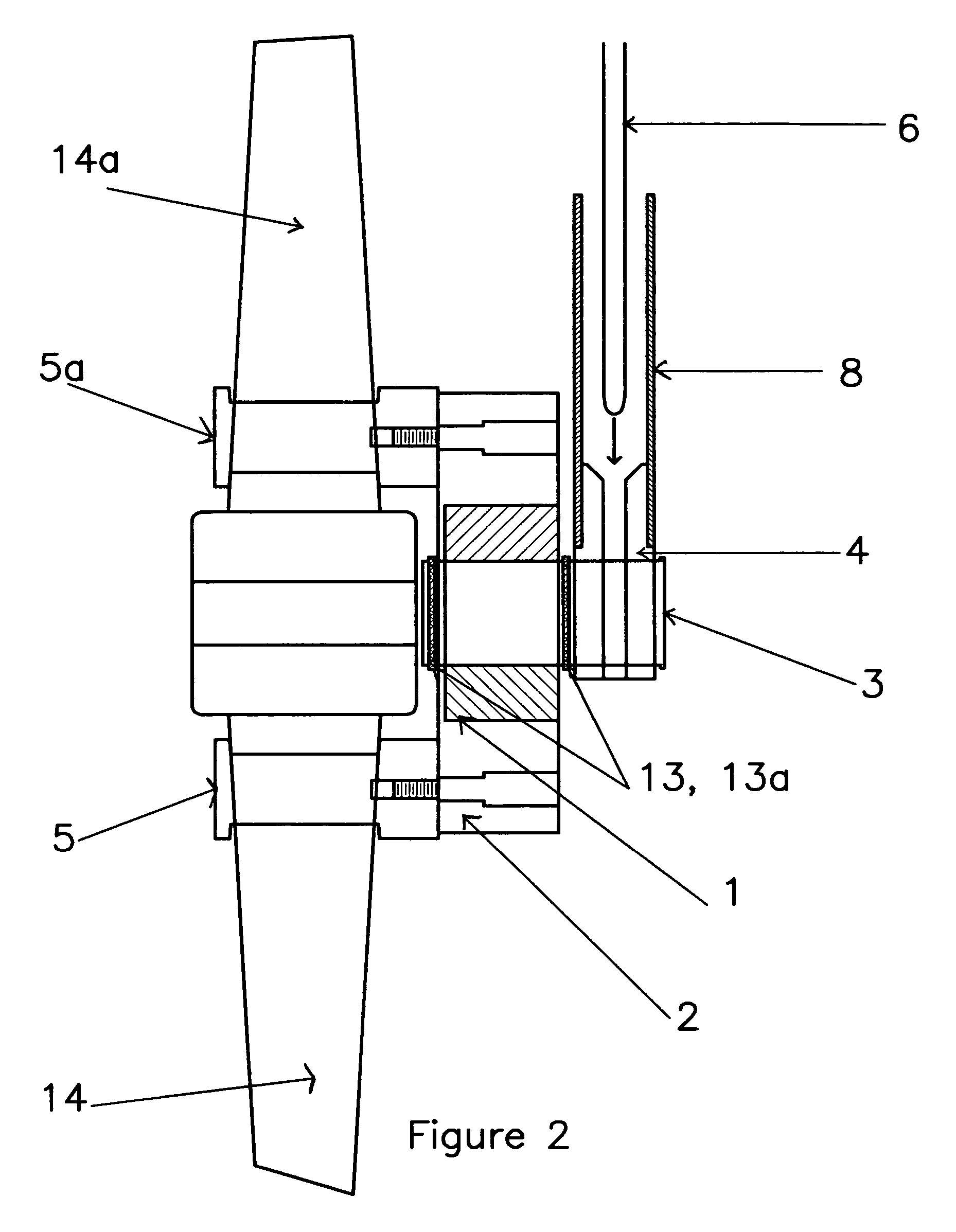
[0027]FIG. 2 shows a cross section of one-way bearing 1 in housing 2 attached to the wheelchair drive wheel spokes 14 / 14a by means of drive lugs 5 / 5a. Said drive lugs, which can be rigidly attached to housing—in this embodiment by threaded fasteners—clamp said spokes. Various embodiments will have a varying numbers of lugs, and various lug cross-sect...


PUM


Abstract

A system for providing a wheelchair user access to forward, neutral and reverse movement while maintaining a continuous grip, silent operation, and allowing for small rotational movements of the wheelchair wheel to be easily made. The system includes a one-way bearing which is attached to a wheelchair wheel such that the center of the one-way bearing is coaxial with the wheelchair wheel axle, a drive axle mounted through the center of said one-way bearing, and a drive rod.

Description

CROSS REFERENCE TO RELATED APPLICATIONS[0001]This application is a continuation in part of U.S. patent application Ser. No. 11 / 049,312, which was filed on Feb. 1, 2005 now abandoned, which is hereby incorporated by reference.BACKGROUND OF THE INVENTION[0002]The present invention relates to a manually operated lever drive system for wheelchairs that attaches as an after-market application to the primary drive wheels. Manually powered wheelchairs are often used by people who have physical impairments that diminish the strength available for propelling the wheelchair. The fundamental physical requirements of an individual utilizing a manual wheelchair are inherently contrary to abilities and limitations of the impaired because in general, and by design, manually powered wheelchairs require the user to grasp a circular hand-ring that is attached to the wheelchair drive wheel. To move the chair, the user is required to grip this ring and apply manual pressure to rotate the hand-ring and ...

Claims


Application Information

Patent Timeline
Patent Type & Authority Patents(United States)
IPC IPC(8): B62M1/14
CPCA61G5/025A61G5/023B62M1/14B62K5/003B62M1/24
Inventor MITTELSTAEDT, MARK
Owner MITTELSTAEDT MARK
Why Eureka
Try Eureka