Polymer pharmceutical pig and associated method of use and associated method of production

Inactive Publication Date: 2005-10-13
MALLINCKRODT INC
34 Cites 11 Cited by

AI-Extracted Technical Summary

Problems solved by technology

The tungsten is an alternative shielding material to lead, but it is much more expensive.
However, because of the possibility of contamination, the lower section of the pharmaceutical pig is washed and disinfected after each use in the Mallinckrodt system of radiopharmacies.
However, both the two-part lead/plastic pharmaceutical pig and the three-part lead/plastic pharmaceutical pig have exposed lead on the interior.
Moreover, lead, as a material, might be construed as being hyg...

Benefits of technology

[0011] Moreover, for convenience and ease of use, the amount of rotation of the elongate polymer cap in relation to the elongate polymer base for removably attaching the elongate polymer base to the elongate polymer cap is minimized, i.e., preferably less than three hundred and sixty degrees (360°), more preferably less than one hundred and eighty degrees (180°) and optimally less than ninety degrees (90°). Preferably, a locking detent is located in the threaded interconnections to secure the elongate polymer base to the elonga...

Abstract

A pharmaceutical pig is used to transport a syringe containing a liquid radiopharmaceutical from a radiopharmacy to a medical facility for administration to a patient. The pharmaceutical pig includes an elongate polymer cap that is removably attached to an elongate polymer base. The elongate polymer cap includes a cap shell that completely encloses a cap shielding element and the elongate polymer base includes a base shell that completely encloses a base shielding element. Preferably the polymer utilized for the cap shell and the base shell is polycarbonate resin, e.g., LEXAN®. An inner liner is not utilized and the cap shielding element and the base shielding element, which are preferably, but not necessarily, made of lead, are completely sealed and unexposed.

Application Domain

Dispensing apparatusSurgical drapes +12

Technology Topic

PolycarbonateSyringe +7

Image

  • Polymer pharmceutical pig and associated method of use and associated method of production
  • Polymer pharmceutical pig and associated method of use and associated method of production
  • Polymer pharmceutical pig and associated method of use and associated method of production

Examples

  • Experimental program(1)

Example

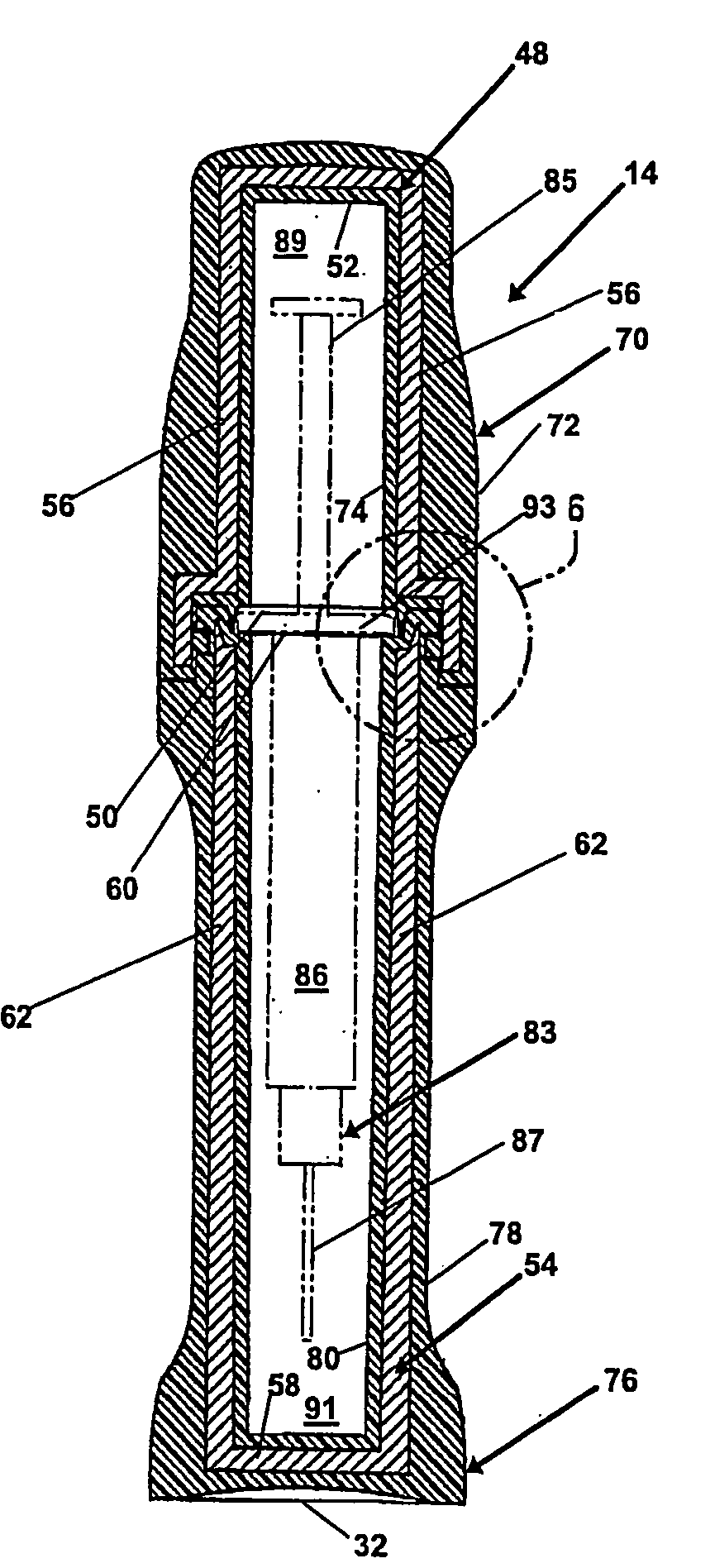
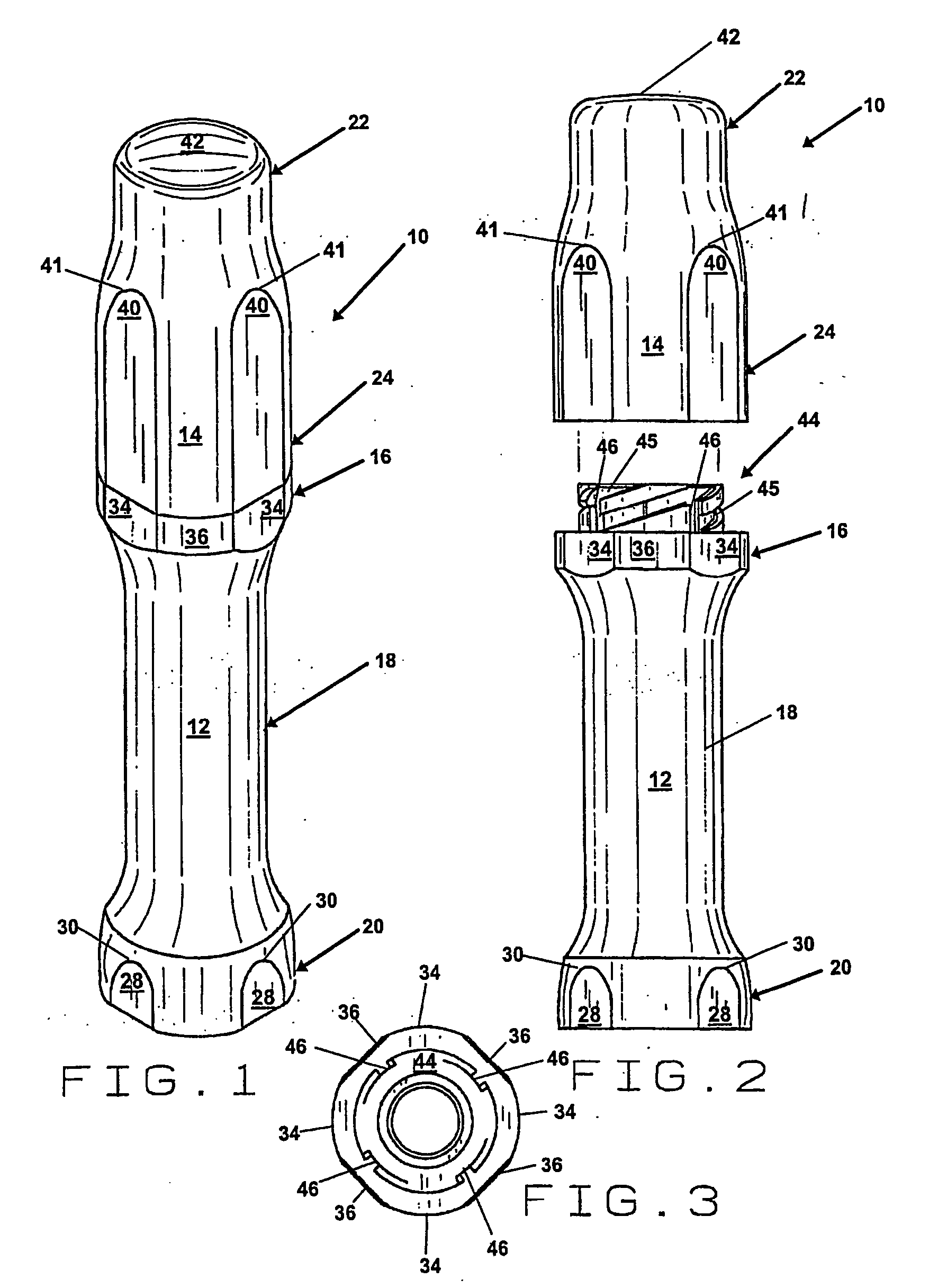
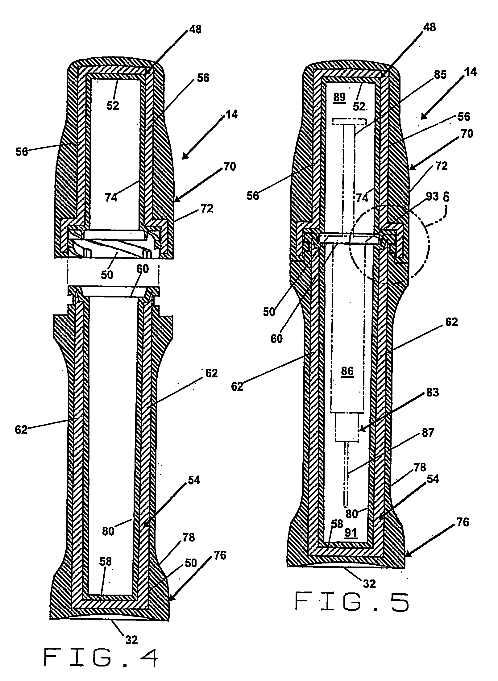
[0025]FIG. 1 is a perspective view of the embodiment of the pharmaceutical pig of the present invention that is generally indicated by numeral 10. There is an elongate base 12 and an elongate cap 14. The elongate base 12 and the elongate cap 14 of the pharmaceutical pig 10 can be formed in any of a wide variety of shapes and sizes, however, a substantially cylindrical shape is preferred. Preferably, the elongate base 12 includes a top portion that is generally indicated by numeral 16 having a first diameter, a middle portion that is generally indicated by numeral 18 having a second diameter and a bottom portion that is generally indicated by numeral 20 having a third diameter. The elongate cap 14 includes a top portion that is generally indicated by numeral 22 having a fourth diameter and a bottom portion that is generally indicated by numeral 24 having a fifth diameter. In the preferred embodiment, the second diameter of the middle portion 18.of the elongate base 12 is less than the first diameter of the top portion 18 of the elongate base 12. The second diameter of the middle portion 18 of the elongate base 12 is also less than the third diameter of the bottom portion 20 of the elongate base 12 to create a bell-shape. Also, in the preferred embodiment, the fourth diameter of the top portion 22 of the elongate cap 14 is less than the fifth diameter of the bottom portion 24 of the elongate cap 14.
[0026] The elongate base 12 for the pharmaceutical pig 10, preferably includes a first plurality of flattened portions 28, e.g., four (4), that each include an arch-like portion 30 located on the bottom portion 20 of the elongate base 12 of the pharmaceutical pig 10. The bottom portion 20 of the elongate base 12 is preferably bell-shaped to prevent tipping and includes a domed, bottom surface 32 to reduce material cost, as shown in FIGS. 4 and 5.
[0027] Referring again to FIGS. 1 and 2, the top portion 16 of the elongate base 12 for the pharmaceutical pig 10, preferably and optionally, includes a second plurality of flattened portions, e.g., four (4), that preferably alternate between rectangular portions 36 and rectangular portions that each have a downwardly extending arch-like portion 34.
[0028] The elongate cap 14 for the pharmaceutical pig 10, preferably and optionally, includes a third plurality of flattened portions 40, e.g., four (4), that each include an arch-like portion 41. The top portion 22 is preferably circular and includes a flat top surface 42, as shown in FIG. 1, which can be labeled as well as easily transported within a delivery case that can hold a multiple number of pharmaceutical pigs 10.
[0029] There is a plurality of threaded interconnections, which is generally indicated by numeral 44, as shown in FIG. 2. Preferably, but not necessarily, there are four (4) threads 45.
[0030] Preferably, with the present pharmaceutical pig 10 of the present invention, the amount of turns required to secure the elongate base 12 to the elongate cap 14 is minimized. The preferred amount of turning being one turn (360°) or less, with a more preferred amount of turning being one-half of a turn (180°) or less and the most preferred amount of turning being one-quarter of a turn (90°) or less. The pitch of the threads 45 can vary greatly depending on the parameters of the pharmaceutical pig 10, with the most preferred value of pitch being 1.38 for the threads 45.
[0031] Referring now to FIG. 3, there is a series of locking detents 46 that secure the elongate base 12 to the elongate cap 14. These locking detents 46 lock the elongate base 12 to the elongate cap 14 when the threads 45 of the elongate cap 14 and the elongate base 12 are completely engaged. The elongate cap 14 is flush against the elongate base 12 after having completed the maximum amount of turning, e.g., one-quarter of a turn (90°) to seal the elongate cap 14 against the elongate base 12 in fluid-tight relationship. This seal is present without the presence of an additional component that requires replacement and maintenance, such as an o-ring.
[0032] Located within the elongate cap 14 and elongate base 12 is a cap shielding element that is generally indicated by numeral 48 and the base shielding element that is generally indicated by numeral 54, respectively, as shown in FIGS. 4 and 5. These shielding elements 48 and 54 are typically formed from lead because it is relatively inexpensive and easy to form. Moreover, these shielding elements 48 and 54 can be formed from any material that blocks the radiation that is emitted from the radiopharmaceutical. For example, tungsten is a suitable shielding element, but it is more expensive than lead and more difficult to form or mold. Metallic-filled polymer composite materials such as the ECOMASS® compounds produced by Engineered Materials, a M. A. Hanna Company having a place of business in Norcross, Ga. can also be used as shielding material.
[0033] The cap shielding element 48 has a closed end 52 and an open end 50. The walls 56 of the cap shielding element 48 are of generally uniform thickness. The base shielding element 54 has a closed end 58 and an open end 60. The walls 62 of the base shielding element 54 are of generally uniform thickness.
[0034] As shown in FIG. 5 and best illustrated in FIG. 6, the walls 62 of the base shielding element 54 form a protrusion 64, which is preferably but not necessarily triangular, which forms an angle T when measured against the inside wall of the base shielding element 54. The base shielding element 54 includes a ledge near the open end 60 that forms a shoulder 66.
[0035] Referring again to FIGS. 4 and 5, the cap shielding element 48 of the elongate cap 14 is completely enclosed by a cap shell 70 having an outer cap shell portion 72 and an inner cap shell portion 74. Also, the base shielding element 54 of the elongate base 12 is completely enclosed by a base shell 76 having an outer base shell portion 78 and an inner base shell portion 80.
[0036] The cap shell 70 and base shell 76 are preferably made of polymer material. This can include virtually any type of plastic, however, the most preferred type of material is a polycarbonate resin. A specific type of polycarbonate resin, which can be utilized with the present invention, can be purchased under the mark LEXAN®, which is a federally registered trademark of the General Electric Company, having a place of business at One Plastics Avenue, Pittsfield, Mass. 01201. LEXAN® is very lightweight, but is also known for its impact resistance, clarity, stability and heat resistance.
[0037] The preferred method of forming the cap shell 70 and base shell 76 so that the cap shell 70 and base shell 76 enclose and seal the cap shielding element 48 of the elongate cap 14 and the base shielding element 54 of the elongate base 12, respectively, is by the process of molding. Although the polymer material can be molded in two parts and then melted or welded to provided the complete enclosure of the cap shielding element 48 of the elongate cap 14 and the base shielding element 54 of the elongate base 12, the preferred method of molding the polymer material is by a “two-shot” or “overmolding” process.
[0038] Examples of this “two-shot” or “overmolding” process are described in: U.S. Pat. No. 4,750,092, which issued to Werther on Jun. 7, 1988 and was assigned to Kollmorgen Technologies Corporation, which is incorporated herein by reference; U.S. Pat. No. 6,381,509, which issued to Thiel et al. on Apr. 30, 2002; and was assigned to Mattec, Inc, which is incorporated herein by reference; and U.S. Pat. No. 6,405,729, which issued to Thornton on Jun. 18, 2002, which is incorporated herein by reference.
[0039] A significant advantage of the present invention is that no inner liner is utilized. This is a significant advantage since inner liners are typically discarded after each use. This reduces cost and eliminates waste.
[0040] As also shown in FIG. 5, there is a syringe 83, having: a needle 87 shown in phantom; a barrel 86; a plunger 85; and finger grips 93 which are sometimes called wings. The finger grips 93 may be hexagonal, circular or polygonal; they may fully or partially surround the barrel 86. The finger grips 93 are captured between the previously described shoulder portion 66 formed in the inner base shell portion 80 of the base shell 76 and the inner cap shell portion 74 of the cap shell 70. The syringe 83 is therefore prevented from lateral movement inside the pharmaceutical pig 10 during transit. The needle 87 and at least a portion of the barrel 86 are positioned in a first hollow center section 91 of the elongate base 12. At least a portion of the plunger 85 is positioned in a second hollow center section 89 of the elongate cap 14.
[0041] The pharmaceutical pig 10 is believed to comply with the revised Bloodborne Pathogens Standard (29 C.F.R Sectional 1910.1030(d)(2)) promulgated by the Occupational Safety and Health Administration by fully meeting their definition of a “sharps container” by providing a container that is: puncture resistant; capable of being labeled or color-coded; leakproof on the sides and bottom; and does not require a healthcare provider to reach by hand into the container where the sharp has been placed.
Method of Use for the Pharmaceutical Pig 10:
[0042] A prescription is called in, faxed in, or otherwise given to a radiopharmacy. The pharmacist enters the prescription in a computer and prints out the labels. A self-adhesive label can be attached to the pharmaceutical pig 10 in a conventional fashion. In the alternative, a label can be attached to the pharmaceutical pig with the flexible sleeve (not shown), without the need for adhesives. A separate label is affixed to a safety syringe or a conventional syringe. The syringe 83 is filled with a radiopharmaceutical in accordance with the prescription. The filled syringe 83 is assayed. In other words, the activity of the radiopharmaceutical in the syringe 83 is measured in a dose calibrator to verify that it complies with the prescription. The filled syringe 83 is put in the pharmaceutical pig 10 and then closed. The pharmaceutical pig 10 is wipe tested for contamination. If the pharmaceutical pig 10 passes the wipe test, it is placed in a delivery container.
[0043] The delivery containers used by some Mallinckrodt Inc. pharmacies have interior padding of rubber foam. Several pharmaceutical pigs 10 may be placed in a single delivery container. Before leaving the radiopharmacy, the delivery container and the pharmaceutical pigs 10 are wipe tested and surveyed. If the delivery container passes, a DOT label is affixed to the outside of the delivery container and it is delivered to a medical facility.
[0044] The pharmaceutical pigs 10 are then opened and the syringe 83 is placed in an injection shield. The radiopharmaceutical is administered to the patient. The delivery case with the pharmaceutical pigs 10 and used syringes 83 are then returned to the radiopharmacy. The syringe 83 is removed from the pharmaceutical pig 10 and placed in a disposal bin. The pharmaceutical pig 10 is then washed and dried. The pharmaceutical pig 10 is then ready to be reused.
Method of Producing the Pharmaceutical Pig 10:
[0045] This involves first molding the base shielding element 54 by pouring molten, nuclear shielding, material into a first mold (not shown). The preferred substance is lead, as opposed to tungsten or metallic-filled polymers, due to cost considerations and ease of molding. When the base shielding element 54 has solidified, the base shielding element 54 is then placed into an injection molding machine (not shown). The polymer material, e.g., polycarbonate resin, is then injected and flows into a third mold, having a mold cavity, which surrounds the base shielding element 54. After an application of temperature and pressure, a solidified elongate base 12 is released from the mold. This elongate base 12 includes the base shielding element 54, which is now completely enclosed by a base shell 76. The base shell 76 includes an inner base shell portion 80 that is adjacent to the needle 87 and barrel 86 of the syringe 83 and an outer base shell portion 78 that forms the outer surface of the elongate base 12. In the same manner, the cap shielding element 48 is created by pouring molten, nuclear shielding, material into a second mold (not shown). As with the base shielding element 54, the preferred substance is again lead. When the cap shielding element 48 has solidified, the cap shielding element 48 is placed into an injection molding machine (not shown). The polymer material, e.g., polycarbonate resin, is then injected and flows into a fourth mold, having a mold cavity, which surrounds the cap shielding element 48. After an application of temperature and pressure, a solidified elongate cap 14 is released from the mold. This elongate cap 14 includes the cap shielding element 48, which is now completely enclosed by the cap shell 70. The cap shell 70 includes an inner cap shell portion 74 that is adjacent to the plunger 85 of the syringe 83 and an outer cap shell portion 72 that forms the outer surface of the elongate cap 14.
[0046] Although a preferred embodiment of the pharmaceutical pig 10, a method of use of the pharmaceutical pig 10 and a method of production for the pharmaceutical pig 10 have been illustrated in the accompanying Drawings and described in the foregoing Detailed Description, it is understood that the invention is not limited to the embodiment disclosed, but is capable of numerous rearrangements, modifications and substitutions without departing from the spirit for the invention as set forth and defined by the following claims.

PUM

PropertyMeasurementUnit
Angle360.0°
Angle90.0°
Diameter

Description & Claims & Application Information

We can also present the details of the Description, Claims and Application information to help users get a comprehensive understanding of the technical details of the patent, such as background art, summary of invention, brief description of drawings, description of embodiments, and other original content. On the other hand, users can also determine the specific scope of protection of the technology through the list of claims; as well as understand the changes in the life cycle of the technology with the presentation of the patent timeline. Login to view more.

Similar technology patents

Apparatus and method for low-density cellular wood plastic composites

InactiveUS20050067729A1less-expensivelow cost
Owner:STRANDEX CORP

Haptic trackball device

InactiveUS7710399B2simple actuatorlow cost
Owner:IMMERSION CORPORATION

Steering Arrangement for a Trailer

InactiveUS20110018231A1low cost
Owner:ZF FRIEDRICHSHAFEN AG

Classification and recommendation of technical efficacy words

  • ease of manufacture
  • low cost

Engaging structure for runner of an umbrella

InactiveUS20050194027A1ease of manufacture
Owner:KO CHIN SUNG

Repeating frame battery with joining of cell tabs via welded-on male and female slip-fit connectors

InactiveUS20120028097A1minimize costease of manufacture
Owner:GM GLOBAL TECH OPERATIONS LLC

Unauthorized access prevention method

InactiveUS20060108416A1ease of manufacturelow cost
Owner:CANON KK

Plasma processing apparatus component and manufacturing method thereof

InactiveUS20080173399A1ease of manufacturereduce deterioration
Owner:TOKYO ELECTRON LTD

Personal blind heat containment apparatus and method therefor

InactiveUS20050016981A1ease of manufacturelow cost
Owner:IRVIN GEORGE

System and method for transmitting wireless digital service signals via power transmission lines

ActiveUS7929940B1reduce bandwidth requirementlow cost
Owner:NEXTEL COMMUNICATIONS

System and method for determination of position

InactiveUS20090149202A1low costreduce requirement
Owner:STEELE CHRISTIAN

Adaptive antenna optimization network

InactiveUS6961368B2low costminimal space
Owner:ERICSSON INC

Antenna device and method for attaching the same

ActiveUS20150138022A1low costimproved strength characteristic
Owner:NEC CORP
Why Eureka
Try Eureka