Electrode and method of manufacture

a plasma display panel and electrode technology, applied in the manufacture of electrode systems, cold cathode manufacturing, electric discharge tube/lamp manufacture, etc., can solve the problems of weakened electrodes, easy to break, and patterned side cuts

Inactive Publication Date: 2009-07-07
AU OPTRONICS CORP
View PDF15 Cites 57 Cited by
  • Summary
  • Abstract
  • Description
  • Claims
  • Application Information

AI Technical Summary

Benefits of technology

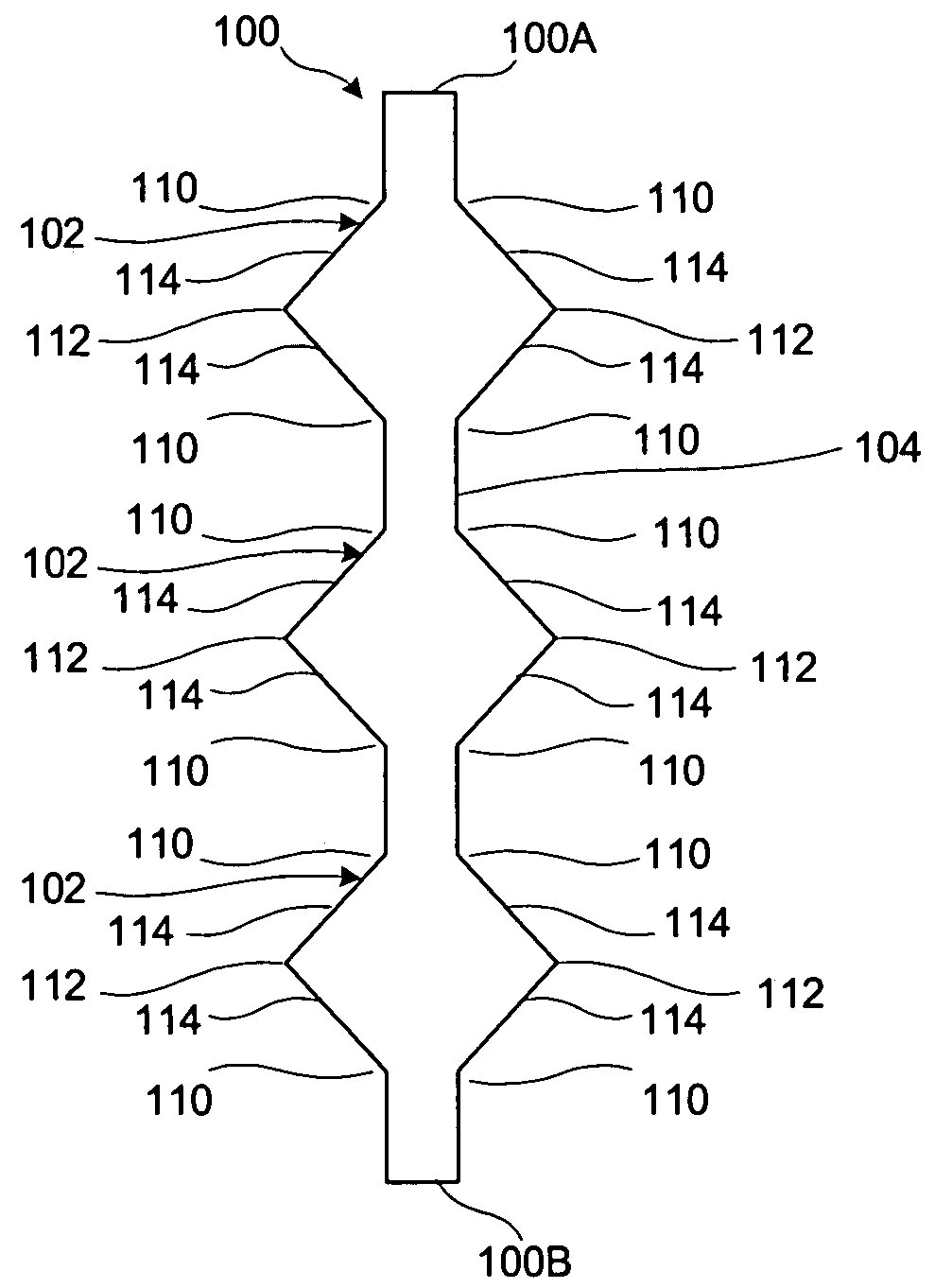
[0009]According to an embodiment of the invention, the electrode profile is made to be streamlined or curved, such that developer flow avoids erosion of a side cut at a sharp angle in the profile of a patterned mask that would cause an electrode break.
[0010]According to another embodiment of the invention, the line width of the electrode changes gradually from narrow to wide, which avoids causing an electrode break during the firing process.

Problems solved by technology

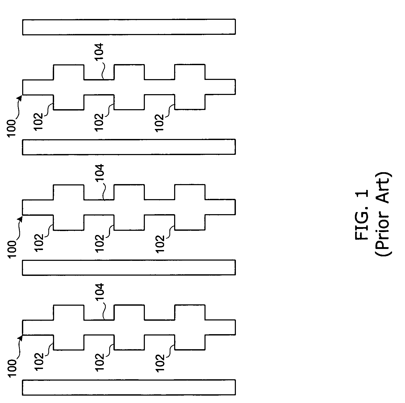
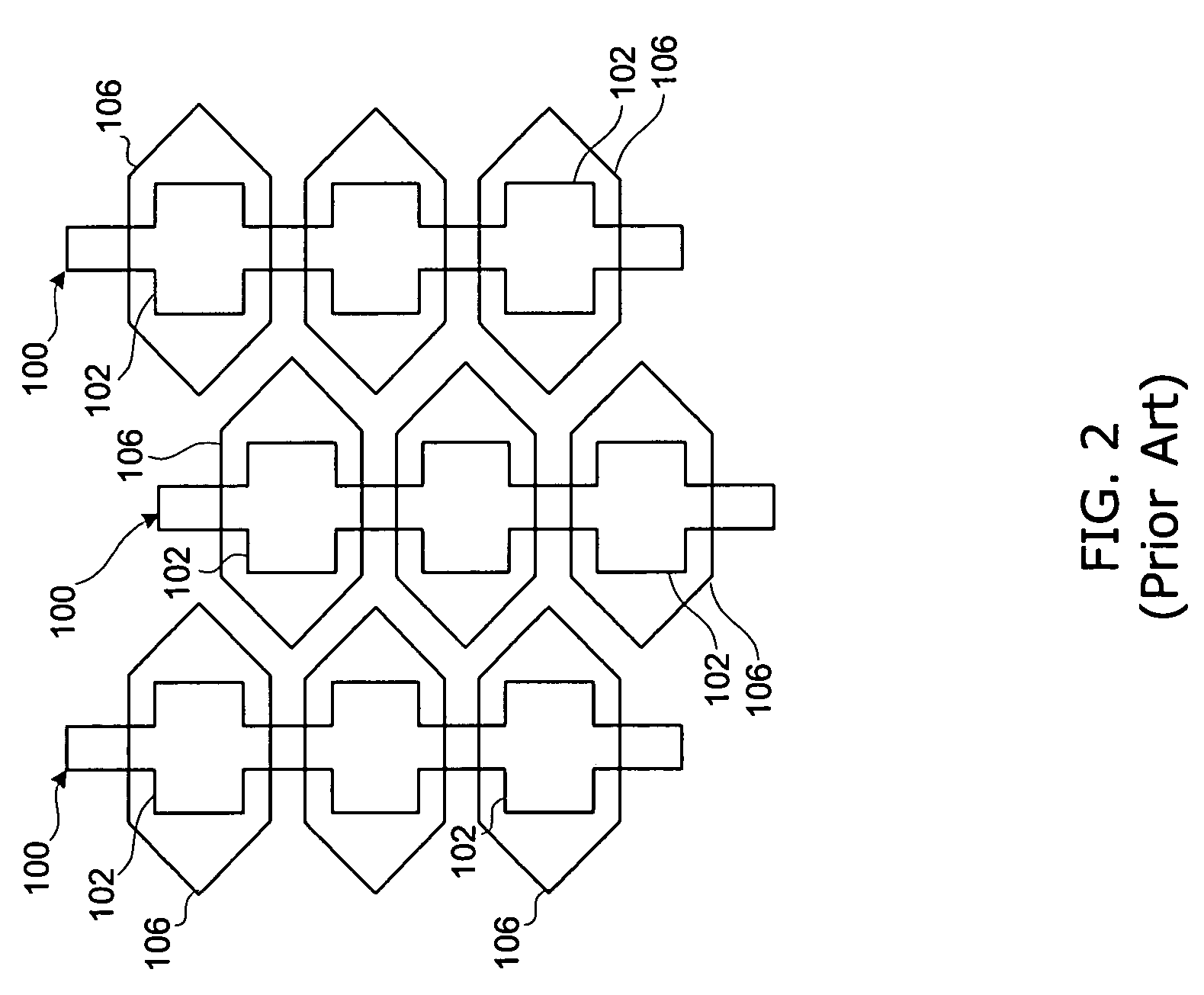
The side cuts in the patterned mask are transferred to the electrodes, which make electrodes that are weakened by patterned side cuts, and susceptible to a break.

Method used


Image

  • Electrode and method of manufacture
  • Electrode and method of manufacture
  • Electrode and method of manufacture

Examples


Embodiment Construction

[0025]This description of the exemplary embodiments is intended to be read in connection with the accompanying drawings, which are to be considered part of the entire written description. In the description, relative terms such as “lower,”“upper,”“horizontal,”“vertical,”, “above,”“below,”“up,”“down,”“top” and “bottom” as well as derivative thereof (e.g., “horizontally,”“downwardly,”“upwardly,” etc.) should be construed to refer to the orientation as then described or as shown in the drawing under discussion. These relative terms are for convenience of description and do not require that the apparatus be constructed or operated in a particular orientation. Terms concerning attachments, coupling and the like, such as “connected” and “interconnected,” refer to a relationship wherein structures are secured or attached to one another either directly or indirectly through intervening structures, as well as both movable or rigid attachments or relationships, unless expressly described othe...


PUM


Abstract

An electrode on a substrate of a plasma display panel has a relatively narrow bus line conductor at an intersection with a pad, and a line width of the pad being wider than a line width of the bus line conductor and substantially narrower than a line width of a wider section of the pad, which avoids a break in the electrode when the electrode is fired at an elevated temperature.

Description

FIELD OF THE INVENTION[0001]The present invention relates to an electrode for a plasma display panel, PDP, and to a method of manufacturing the electrode on a substrate of a PDP.BACKGROUND[0002]A plasma display panel has a substrate on which electrodes are fabricated by performing industry known, photolithographic process steps. First, a photo resist covers a layer of electrode material on the substrate. The, according to a development process, photolithographic patterning is performed by directing a beam of electromagnetic radiation through a patterned photolithographic mask. The beam is patterned by the mask, and is focused to irradiate a photo resist layer with an un-irradiated pattern. Then, the patterned photo resist layer is washed with a developer to remove the non-irradiated part, which leaves behind a patterned photo resist. The patterned photo resist covers a layer of electrode material on the substrate.[0003]With the patterned photo resist in place, selective etching is p...

Claims


Application Information

Patent Timeline
Patent Type & Authority Patents(United States)
IPC IPC(8): H01J17/49H01J11/02H01J17/04
CPCH01J9/02H01J11/24H01J2211/245
Inventor WU, YI-JENSUNG, WEN-FA
Owner AU OPTRONICS CORP
Why Eureka
Try Eureka