
Power converter with emulated peak current mode control

Inactive Publication Date: 2009-07-07
DIALOG SEMICONDUCTOR
View PDF10 Cites 33 Cited by
  • Summary
  • Abstract
  • Description
  • Claims
  • Application Information

AI Technical Summary

Benefits of technology

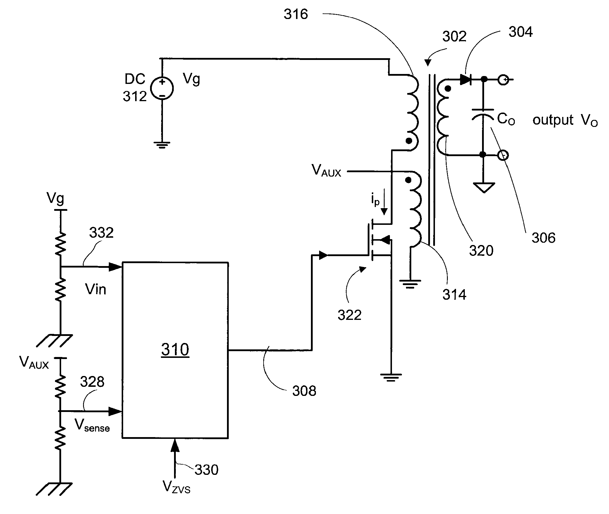
[0011]An embodiment of the present invention includes a power converter including a switch controller that can emulate peak current mode control without using a resistor to sense a primary peak current of the power converter. Specifically, the power converter according to an embodiment of the present invention detects the primary peak current from a representation of an input voltage and a control voltage to emulate the peak current mode control. The control voltage is an integration of an error voltage between a reference voltage and a representation of an output voltage of power converter. Based on the detected peak current, the power converter generates a pulse signal for a second switching cycle subsequent to a first switching cycle so that the primary peak current does not exceed a maximum limit.
[0012]In an embodiment of the present invention, a digital logic of the switch controller generates a pulse signal for controlling on-times and off-times of the switch based on a digital representation of the input voltage and the control voltage. The digital logic may increase the on-time of the pulse signal in the second switching cycle when the control voltage is greater than the digital representation of the input voltage. When the digital representation of the input voltage is greater than the control voltage, the digital logic decreases the on-time of the pulse signal in the second switching cycle.
[0013]In an embodiment of the present invention, short circuit or overload protection to avoid saturation of a transformer in the power converter is provided. The short circuit or overload protection may be accomplished by comparing a transformer reset time of the transformer with the off-time of the switch in the first switching cycle. When the transformer reset time is longer than the off-time of the switch in the first switching cycle, a switching period of the second switching cycle is increased to allow the transformer to reset in the second switching cycle.

Problems solved by technology

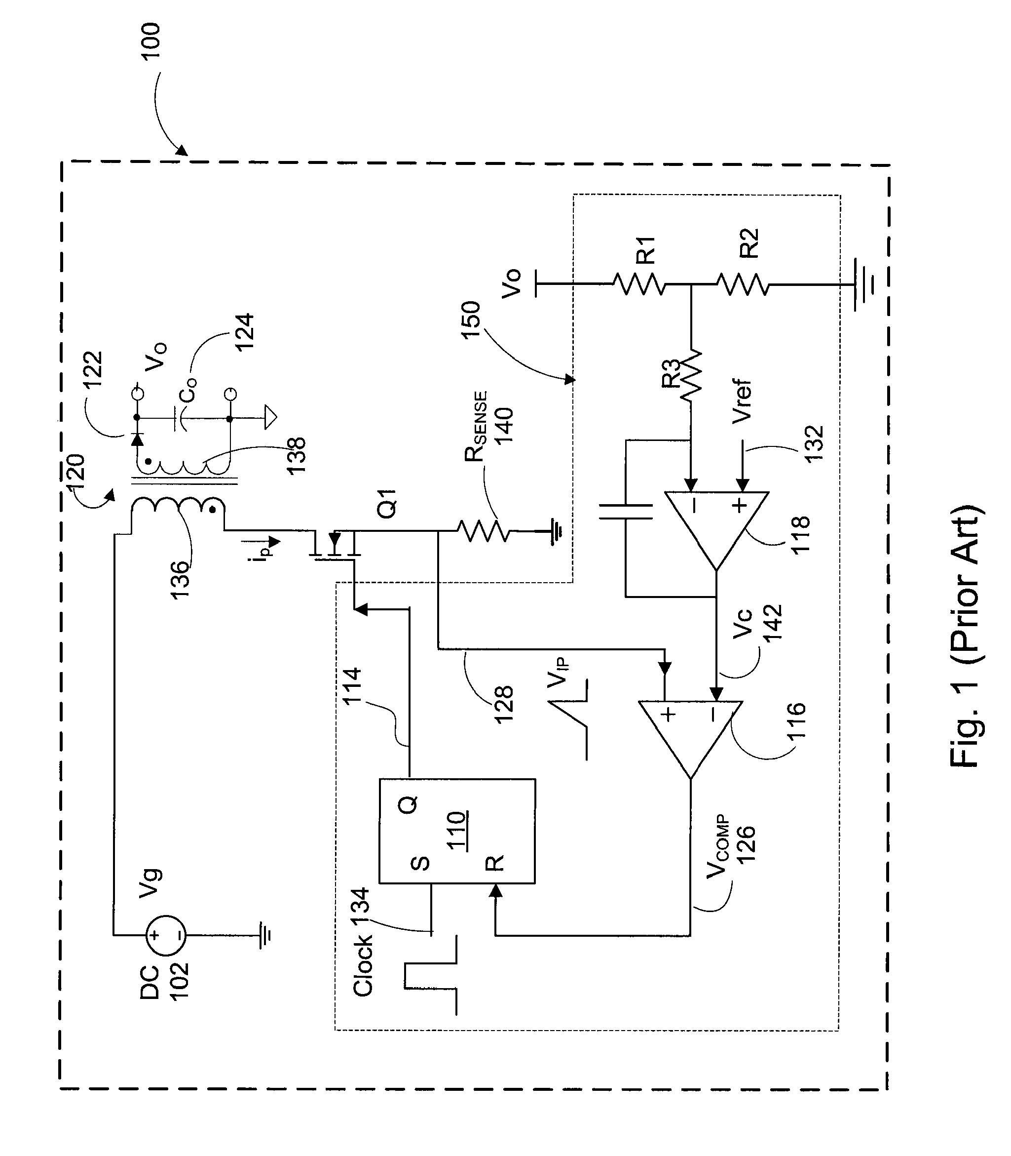
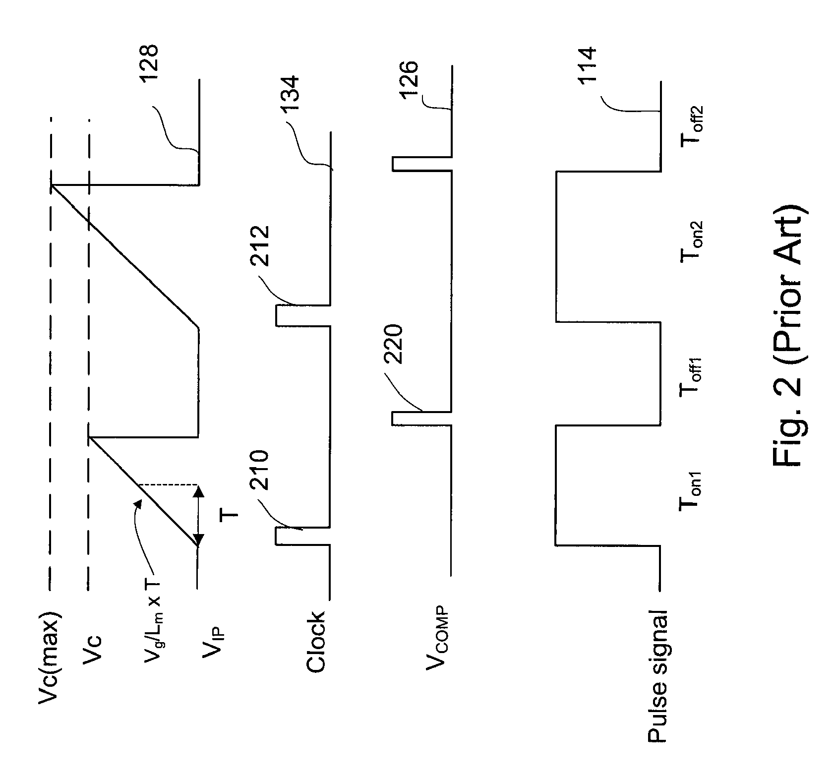
The saturation of the transformer can in turn cause an excessive current in the switch Q1 and damage the switch Q1.
The resistor Rsense 140 for sensing the primary peak current ip, however, reduces efficiency and reliability of the power converter 100, increases the size of the power converter and adds cost to manufacturing of the power converter.
Moreover, the resistor Rsense reduces the reliability of the power converter because the Rsense consumes a large amount of power and generates heat.

Method used


Image

  • Power converter with emulated peak current mode control
  • Power converter with emulated peak current mode control
  • Power converter with emulated peak current mode control

Examples


Embodiment Construction

[0026]The Figures (FIG.) and the following description relate to preferred embodiments of the present invention by way of illustration only. It should be noted that from the following discussion, alternative embodiments of the structures and methods disclosed herein will be readily recognized as viable alternatives that may be employed without departing from the principles of the claimed invention.

[0027]Reference will now be made in detail to several embodiments of the present invention(s), examples of which are illustrated in the accompanying figures. It is noted that wherever practicable similar or like reference numbers may be used in the figures and may indicate similar or like functionality. The figures depict embodiments of the present invention for purposes of illustration only. One skilled in the art will readily recognize from the following description that alternative embodiments of the structures and methods illustrated herein may be employed without departing from the pr...


PUM


Abstract

A power converter includes a switch controller generating a pulse signal controlling a switch to emulate peak current mode control. The switch controller generates a control voltage from a representation of an output voltage of the power converter and a reference voltage. Based on the control voltage and a representation of an input voltage of the power converter, the switch controller determines a peak current in that switching cycle. If the peak current detected exceeds a maximum peak current, an on-time of the pulse signal in the next switching cycle is decreased. The power converter also provides short circuit or overload protection by increasing an off-time of the pulse signal until the off-time exceeds a transformer reset time of a transformer. If the switch period increased to prevent short circuit or overload exceeds a limit, the pulse signal is shut off immediately.

Description

CROSS-REFERENCE TO RELATED APPLICATION[0001]This application claims priority under 35 U.S.C. §119(e) to co-pending U.S. Provisional Patent Application No. 60 / 735,522 entitled “Digital Off-Line Low-Power Supply Controller,” filed on Nov. 10, 2005, which is incorporated by reference herein in its entirety.BACKGROUND OF THE INVENTION[0002]1. Field of the Invention[0003]The present invention relates generally to a power converter, and more specifically, to a power converter emulating a peak current mode control where on-times of the switch for coupling or decoupling a load to or from a power source is determined by a primary peak current of the power converter.[0004]2. Description of the Related Art[0005]Control schemes for controlling power converters include, among other schemes, peak current mode control. The peak current mode control is a control scheme especially advantageous to high power applications. In the peak current mode control scheme, a power converter controller detects t...

Claims


Application Information

Patent Timeline
IPC IPC(8): H02M3/24H02M7/44H02M3/335
CPCH02M3/33515
Inventor ZHENG, JUNJIE
Owner DIALOG SEMICONDUCTOR
Learn More