Switch device with rapid opening and closing between movable and stationary contacts

a switch and contact technology, applied in contact mechanisms, electrical equipment, cycle equipment, etc., can solve the problems such as the inability of waterdrops such as rainwater drops to reside between the contacts, and achieve the effects of reducing the generation of sparks, reducing friction, and strong impact and friction

Active Publication Date: 2009-07-14
TOYO DENSO
View PDF6 Cites 9 Cited by
  • Summary
  • Abstract
  • Description
  • Claims
  • Application Information

AI Technical Summary

Benefits of technology

[0008]With the first feature of the present invention, the control plunger is urged in the direction to abut on the sliding surface by the urging force of the control spring, so that the movable contact holder is rapidly tilted about the second pivotal shaft to the side to which the tip end of the control plunger proceeds every time the tip end of the control plunger crosses from one side to the other side of the plane extending between the axes of the first and second pivotal shafts. Therefore, when the movable contact holder rapidly turns to the first actuation position, the movable contact is brought into contact with the stationary contact with an impact, thereby effectively removing interjacent objects such as oxide film and dust from between the contact portions, and minimizing generation of sparks. Thus, it is possible to bring the switch into a desirable turned-on state regardless of the operation speed of the control knob. Also, when the movable contact holder is rapidly turned to the second actuation position, the movable contact is rapidly separated from the stationary contact, thereby bringing the switch into a desirable turned-off state regardless of the operation speed of the control knob. With this arrangement, the durability of the switch is improved.
[0009]Further, in a non-contact state between the stationary contact and the movable contact, only a space exists between the contacts, and thus waterdrops such as rainwater drops cannot reside between the contacts. Therefore, it is possible to avoid a short-circuit failure due to the waterdrops residing between the contacts. In this structure, the gap between the contacts in a non-contact state can be sufficiently decreased as compared with the case of a movable-contact sliding type, thereby downsizing the switch.
[0011]With the second feature, as the movable contact turns to one of the actuation positions of the movable contact holder, the contact part of the elastic contact piece of the movable contact is brought into contact with an impact with the stationary contact and at the same time the elastic contact piece is bent, thereby giving a strong impact and friction between the contact portions between the stationary contact and the movable contact. Therefore, it is possible to effectively remove interjacent objects such as oxide film and dust from between the contact portions, and minimize generation of sparks. Also, in a state in which the movable contact holder is kept at one of the actuation position, the elastic contact piece of the movable contact bends while abutting on the stationary contact. Therefore, the contact pressure between the movable contact and the stationary contact is determined not by the strong urging force of the spring, but by the repulsive force due to the bending of the elastic contact piece. Thus, it is possible to prevent the contact pressure by the elastic contact piece from becoming excessive, thereby contributing to improvement of the durability of the contacts.

Problems solved by technology

Further, in a non-contact state between the stationary contact and the movable contact, only a space exists between the contacts, and thus waterdrops such as rainwater drops cannot reside between the contacts.

Method used


Image

  • Switch device with rapid opening and closing between movable and stationary contacts
  • Switch device with rapid opening and closing between movable and stationary contacts
  • Switch device with rapid opening and closing between movable and stationary contacts

Examples


Embodiment Construction

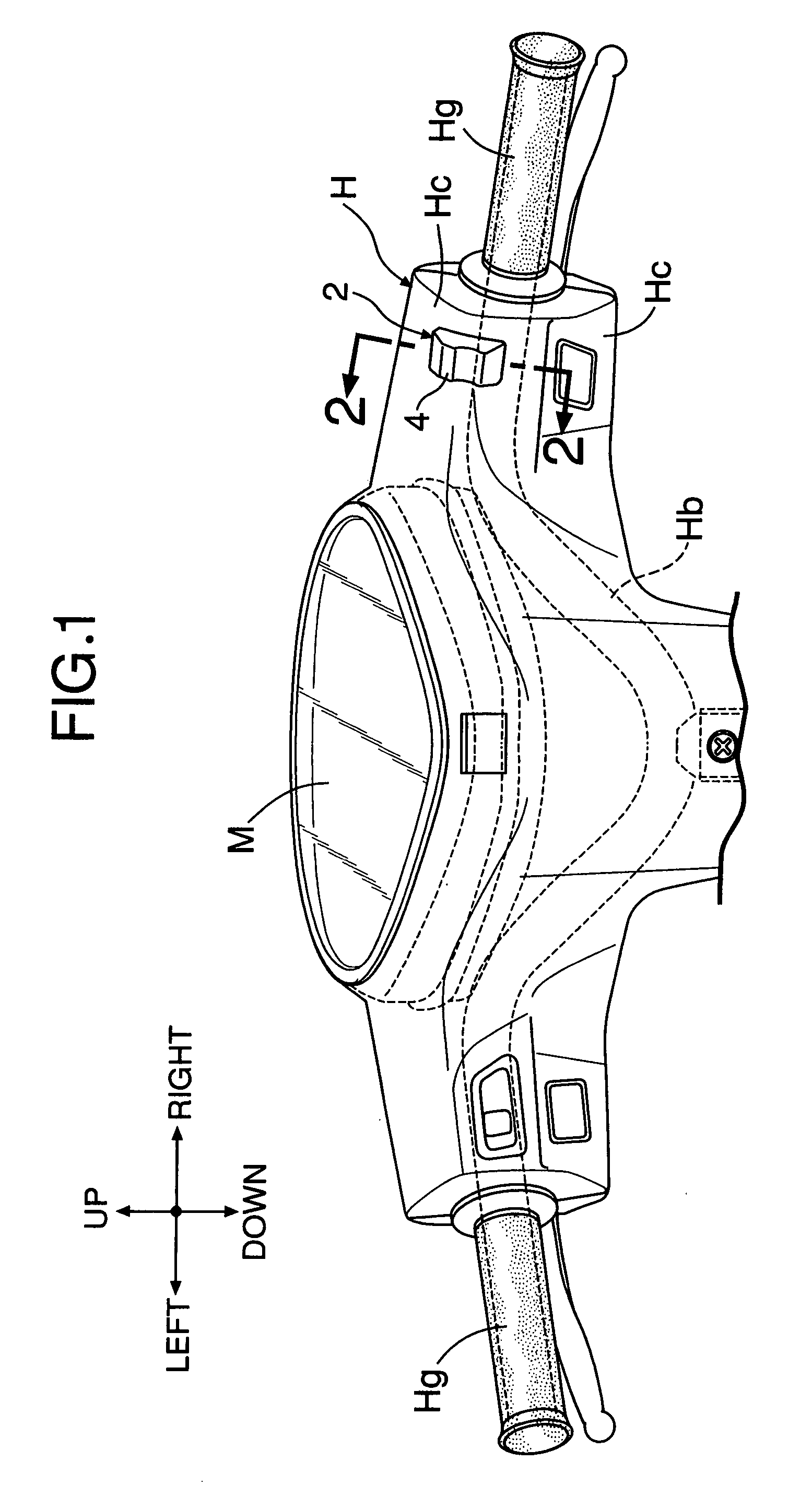
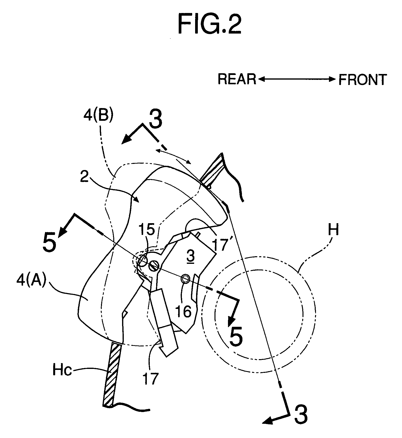
[0021]First, in FIG. 1, a steering handle system H for a motorcycle comprises a handle bar Hb and a handle cover Hc. The handle bar Hb is connected to an upper end of a front fork not shown, and has grips Hg at its opposite end. The handle cover Hc covers an intermediate portion of the handle bar Hb except for the grips Hg. The handle cover Hc is secured by screws to the handle bar Hb at an appropriate position. Various switches are attached to a rear wall, facing the driver, of the handle cover Hc. An engine kill-switch 2 to which the present invention is applied is attached to an upper part of a right end part of the handle cover Hc. A meter unit M including a combination of various meters is attached to an upper part of the handle cover Hc.

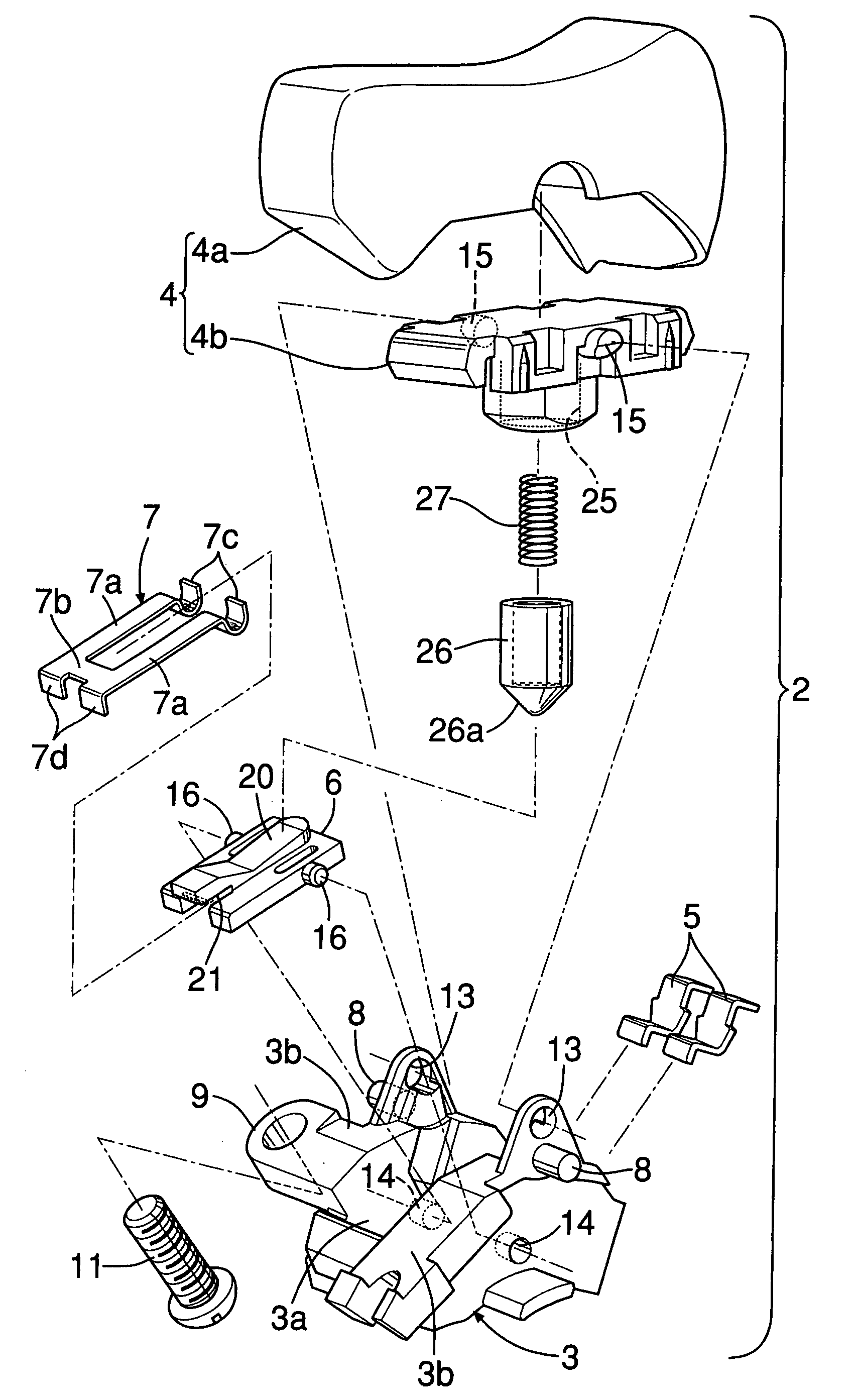
[0022]In FIGS. 2 to 6, the kill-switch 2 includes major components: a switch base 3 fixed to the handle cover Hc; a control knob 4; a pair of left and right stationary contacts 5, 5; a movable contact holder 6; and a movable contact 7.

[0023]The...


PUM


Abstract

A control knob is supported on a switch base via a first pivotal shaft. A movable contact holder holds a movable contact, faces an inner side face of the control knob, and is supported on the switch base via a second pivotal shaft. The movable contact holder is provided with a sliding surface which faces the control knob. A control plunger whose tip end slidably abuts on the sliding surface is fitted to the control knob so as to be slidable in a direction perpendicular to an axis of the first pivotal shaft. A spring is provided between the control knob and the control plunger so as to urge the control plunger to a direction to but on the sliding surface. The movable contact is attached to the movable contact holder so as to come into contact with the stationary contact when the movable contact holder is turned to at least one of first and second actuation positions. Thus, it is possible to provide a switch which enables a rapid opening and closing between a movable contact and a stationary contact by imparting a snap action to the movable contact.

Description

BACKGROUND OF THE INVENTION[0001]1. Field of the Invention[0002]The present invention relates to an improvement of a switch, comprising: a switch base; a stationary contact fixed to the switch base; a control knob attached to the switch base so as to be movable between a first operating position and a second operating position; a movable contact holder which is movable in association with the movement of the control knob to the first and second operation positions; and a movable contact which is supported by the movable contact holder and comes into and out of contact with the stationary contact in response to the movement of the movable contact holder.[0003]2. Description of the Related Art[0004]Such a switch has been already known as disclosed in Japanese Patent Application Laid-open No. 9-323682.[0005]In the conventional switch, movable contacts are of a sliding type. It is desirable that the speed of the movable contact in coming into and out of contact with the stationary conta...

Claims


Application Information

Patent Timeline
Patent Type & Authority Patents(United States)
IPC IPC(8): H01H21/00B62J99/00
CPCH01H23/205
Inventor OKATANI, SHOJINAKATA, HIROKAZU
Owner TOYO DENSO
Why Eureka
Try Eureka