
Vibrotactile haptic feedback devices

a haptic feedback and vibrotactile technology, applied in the field of vibrotactile haptic feedback devices, can solve the problems of severely restricting the force feedback effect, unable to change the natural frequency of a moving,

Inactive Publication Date: 2009-07-14
IMMERSION CORPORATION
View PDF198 Cites 125 Cited by
  • Summary
  • Abstract
  • Description
  • Claims
  • Application Information

AI Technical Summary

Benefits of technology

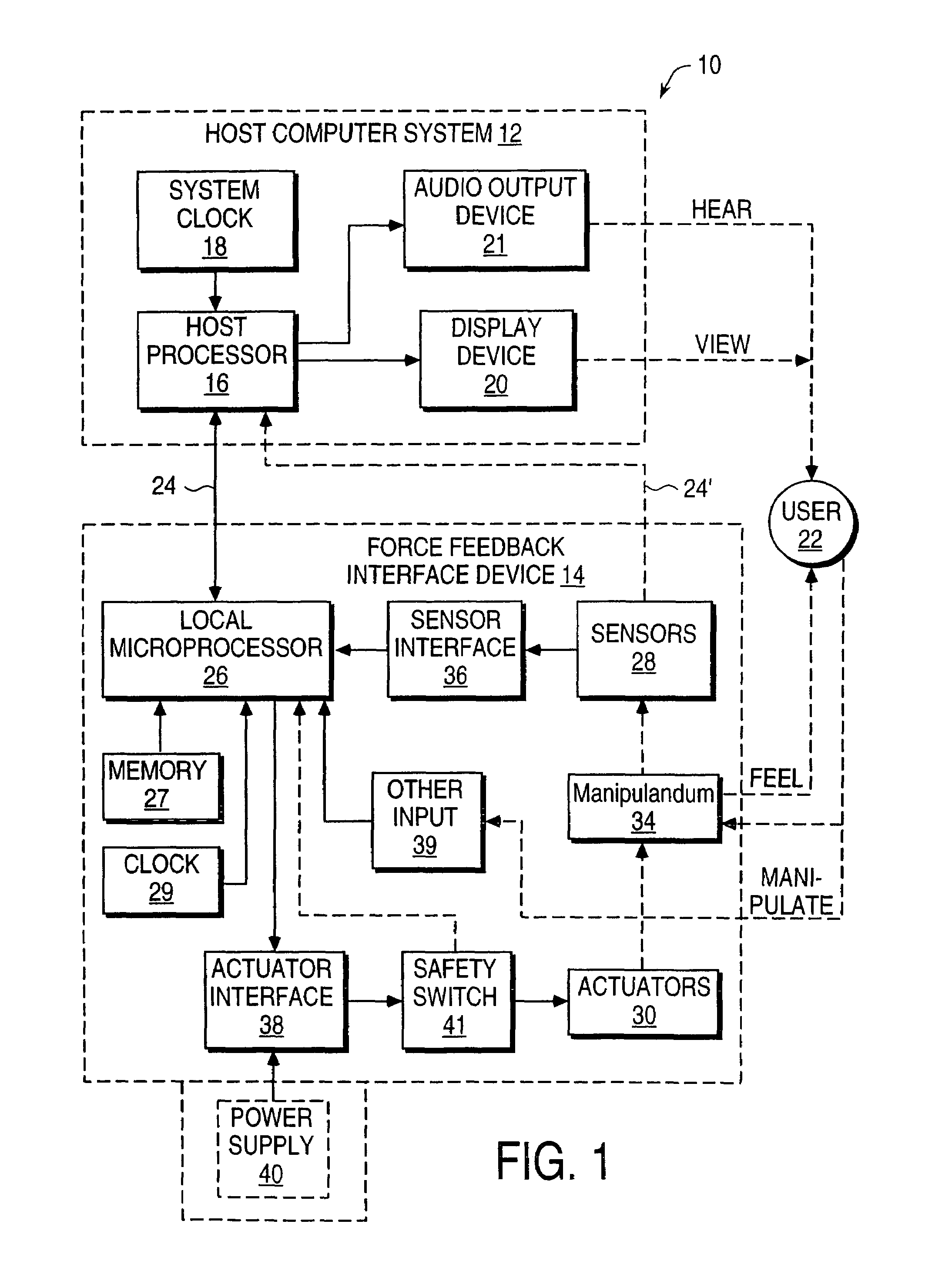
[0008]The present invention is directed to controlling vibrotactile sensations in haptic feedback devices which are interfaced with a host application program. The present invention allows more varied and complex sensations to be provided using inexpensive electronics and mechanical parts.
[0009]More specifically, in one aspect of the present invention, a haptic feedback device for providing vibrotactile sensations to a user is coupled to a host computer. The haptic feedback device, such as a gamepad controller, mouse, remote control, etc., includes a housing grasped by the user, an actuator coupled to the housing, and a mass. The mass can be oscillated by the actuator and a coupling between the actuator and the mass or between the mass and the housing has a compliance that can be varied. Varying the compliance allows vibrotactile sensations having different magnitudes for a given drive signal to be output to the user grasping the housing.
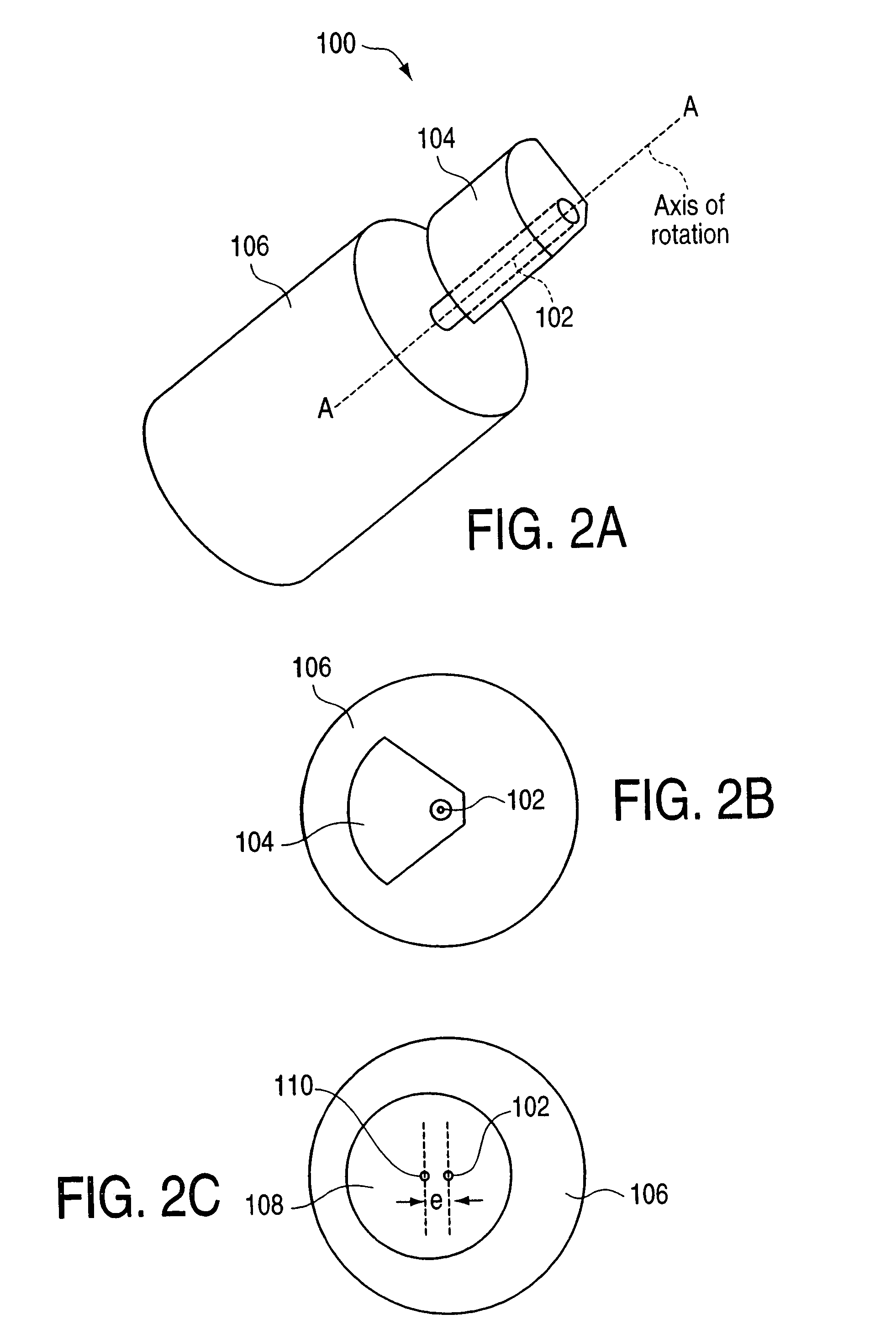
[0011]In another aspect of the present invention, a haptic feedback device for providing vibrotactile sensations to a user is coupled to a host computer and includes a housing grasped by the user, a rotary actuator coupled to the housing, and an eccentric mass coupled to and rotatable by the actuator about an axis of rotation. The eccentric mass has an eccentricity that can be varied relative to the axis of rotation while the mass is rotating. Varying said eccentricity allows vibrotactile sensations having different magnitudes for a given drive signal to be output to the user grasping said housing.
[0013]The present invention advantageously provides a haptic feedback device that can output a wide variety of vibrotactile sensations. Both the frequency and amplitude of the vibrations can be controlled using bi-directional control features. Furthermore, a compliance between mass and ground and / or an eccentricity of the moving mass can be changed to change the natural frequency of oscillation of the mass, providing different vibration magnitudes for a given drive waveform. These features allow a much more efficient use of power for a desired vibration magnitude, a greater precision in the control of vibration sensations, and a wider range of sensations to be experienced by the user than in the prior art devices.

Problems solved by technology

One problem with prior art vibrotactile devices is their ability to change the natural frequency of a moving mass in the actuator system, which is the frequency at which the magnitude of the output vibrations are the highest for a given power input.
The prior art devices thus severely limit the force feedback effects which can be experienced by a user of these devices.

Method used


Image

  • Vibrotactile haptic feedback devices
  • Vibrotactile haptic feedback devices
  • Vibrotactile haptic feedback devices

Examples


embodiment 100

[0063]FIG. 3a is a top plan view of one implementation 100 using magnetic springs. Embodiment 100 provides a magnet 102 grounded to the device's housing 104 with a coil 106 wound around it. A yoke 108 is coupled to a magnet 110a one side and a magnet 110b on its other side, and holds the magnets 110 on each end of the fixed magnet 102. The magnets can be aligned approximately co-axially and can be oriented with north and south facings as shown. The yoke is rotatably coupled to a pivot 112, which is grounded (to the housing, for example), so that the yoke can rotate about an axis B. Current is flowed through the coil 106 from a current source, which can be used to add or subtract from (or cancel) the internal magnetic field between magnets 102 and 110 and which in turn influences the stiffness of the forces between yoke 108 and magnet 102, thereby adjusting the compliance of the suspension between yoke and housing. Current is flowed through the coil 106 as an oscillating (e.g. period...

embodiment 172

[0070]FIG. 6 is a schematic view of a different embodiment 172 of an actuator assembly which provides a variable flexibility between mass and housing. A grounded rotary actuator 173 rotates a lead screw 174. A clamp 175 is coupled to the lead screw 174 at a threaded bore 176 in the clamp so that the clam 175 moves along the lead screw as the screw is rotated. A cantilever 176 is grounded at one end, is threaded through rollers 177 or other clamp elements, and is coupled to a magnetic mass 178 at its other end. A coil 179 and core 181 are grounded and positioned adjacent to the mass 178. When a current is flowed through the coil 179, the magnetic force causes the mass 178 to move; driving current having a forcing function causes the mass 178 to move back and forth as shown by arrows 183, causing a vibration in the housing. This configuration allows independent control over frequency and magnitude of the vibrations when inputting different drive waveforms. The cantilever 176 is flexib...

embodiment 400

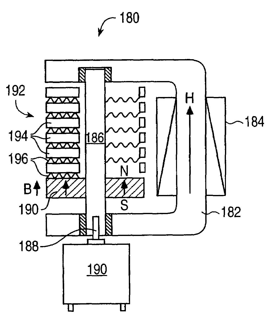
[0095]FIG. 14 is a schematic diagram of a solenoid embodiment 400 of an actuator assembly which provides linear oscillations and vibrations to the housing of an interface device. A core 402 made of iron or steel is positioned between a coil 404 wrapped around a cylindrical housing 406. A south pole magnet 408 is positioned on one side of the core 402, and a north pole magnet 410 is positioned on the other side of the core 402. A core end 412 is made of iron or steel and is positioned adjacent to the south pole magnet 408. Another north pole magnet 414 is positioned on the other side of the core end 412. The two north pole magnets 410 and 414 at the ends of the assembly act as non-linear springs which center the south pole magnet 408 within the coil 404.

[0096]The external magnetic field from the coil 404, caused by flowing current therethrough, is used to move the magnets 402 and 408 and core 402 linearly, as shown by arrow 416. By oscillating the current in the coil, these parts are...


PUM


Abstract

Method and apparatus for controlling magnitude and frequency of vibrotactile sensations for haptic feedback devices. A haptic feedback device, such as a gamepad controller, mouse, remote control, etc., includes a housing, an actuator coupled to the housing, and a mass. In some embodiments, the mass can be oscillated by the actuator and a coupling between the actuator and the mass or between the mass and the housing has a variable compliance. Varying the compliance allows vibrotactile sensations having different magnitudes for a given drive signal to be output. In other embodiments, the actuator is a rotary actuator and the mass is an eccentric mass rotatable by the actuator about an axis of rotation. The eccentric mass has an eccentricity that can be varied relative to the axis of rotation while the mass is rotating. Varying the eccentricity allows vibrotactile sensations having different magnitudes for a given drive signal.

Description

CROSS REFERENCE TO RELATED APPLICATIONS[0001]This application is a continuation of U.S. application Ser. No. 10 / 777,636, filed on Feb. 13, 2004, now abandoned which is a continuation of U.S. application Ser. No. 09 / 643,898, filed on Aug. 18, 2000, entitled “Vibrotactile Haptic Feedback Devices,” now U.S. Pat. No. 6,693,622, and also claims priority to U.S. Provisional Application No. 60 / 149,782, filed Aug. 18, 1999, entitled “Vibration Force Feedback Device Implementations,” and which is incorporated by reference herein, and this application is a continuation-in-part of U.S. patent application Ser. No. 09 / 608,125, filed Jun. 30, 2000, now abandoned entitled, “Controlling Vibrotactile Sensations for Haptic Feedback Devices,” which claims priority to U.S. Provisional Application No. 60 / 142,155, filed Jul. 1, 1999, all of which are incorporated by reference herein.STATEMENT REGARDING FEDERALLY SPONSORED RESEARCH[0002]Certain inventions described herein were made with Government support...

Claims


Application Information

Patent Timeline
Patent Type & Authority Patents(United States)
IPC IPC(8): G09G5/00G06F3/00G06F3/01
CPCG06F3/016
Inventor SHAHOIAN, ERIK J.MARTIN, KENNETH M.SCHENA, BRUCE M.MOORE, DAVID F.
Owner IMMERSION CORPORATION
Learn More