Spiral servo patterns with absolute reference point

a technology of absolute reference point and spiral servo, which is applied in the field of spiral servo pattern absolute reference point, can solve the problems of significant cost and time saving, and the cost of stw is high

Inactive Publication Date: 2009-07-14
SEAGATE TECH LLC
View PDF8 Cites 11 Cited by
  • Summary
  • Abstract
  • Description
  • Claims
  • Application Information

AI Technical Summary

Problems solved by technology

In general, a STW is a very expensive piece of capital equipment.
Even a small reduction in the amount of

Method used


Image

  • Spiral servo patterns with absolute reference point
  • Spiral servo patterns with absolute reference point
  • Spiral servo patterns with absolute reference point

Examples


Embodiment Construction

[0040]While this invention is susceptible of embodiments in many different forms, there are shown in the drawings and will herein be described in detail, preferred embodiments of the invention with the understanding that the present disclosure is to be considered as an exemplification of the principles of the invention and is not intended to limit the broad aspects of the invention to the embodiments illustrated.

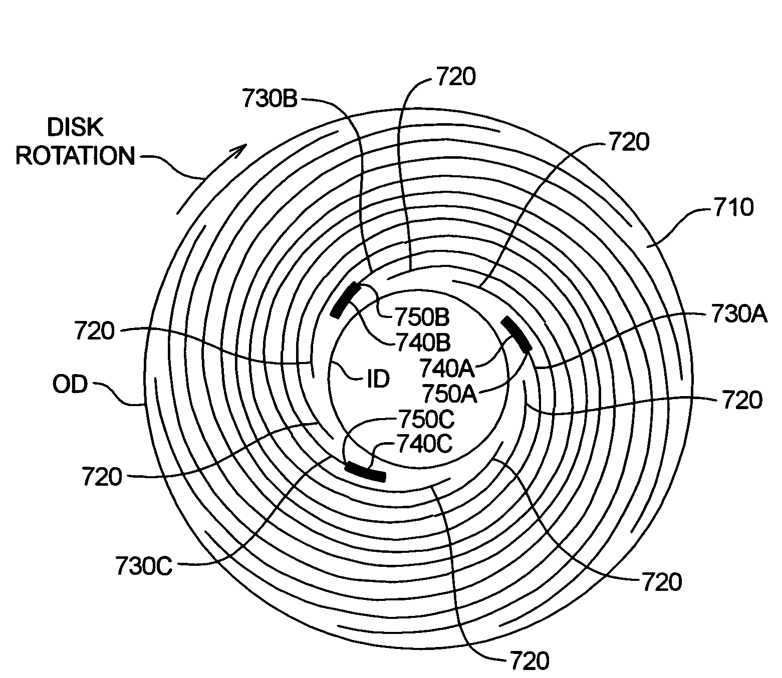
[0041]The present invention is directed to a method for providing an absolute reference point on a disk of a disk drive that has spirals of servo information written thereon. A simplified representation of one embodiment of the invention is shown in FIG. 7.

[0042]The disk surface 710 has spirals of servo information written thereon, wherein some of the spirals of servo information are standard spirals 720 and some are special spirals 730A, 730B and 730C. The special spirals 730A-730C are used to provide an absolute reference position on the disk surface 710 in both the radial...


PUM


Abstract

The present invention is directed to a method and apparatus for providing an absolute reference point on a disk surface of a disk drive. A write head associated with the disk surface is used to write spirals of servo information thereon, for example, under control of a servo track writer. The spirals of servo information include standard spirals and special spirals. In one embodiment, the special spirals are shorter than the standard spirals and the special spirals are rotationally non-symmetric. For example, an unequal number of standard spirals are interposed between one pair of adjacent special spirals relative to the number of standard spirals interposed between other pairs of adjacent special spirals. The special spirals may take a variety of other forms to distinguish themselves from standard spirals.

Description

CROSS-REFERENCE TO RELATED APPLICATIONS[0001]Priority is claimed from U.S. Provisional Patent Application Ser. No. 60 / 475,126 filed Jun. 2, 2003, which is incorporated herein by reference in its entirety.FIELD OF THE INVENTION[0002]The present invention relates generally to data storage devices, such as disk drives. More particularly, the present invention relates to a method and apparatus for providing an absolute reference point on a disk of a disk drive that has spiral servo patterns written thereon.BACKGROUND OF THE INVENTION[0003]Computer disk drives store information on magnetic disks. Typically, the information is stored on each disk in concentric tracks that are divided into sectors. Information is written to and read from a disk by a transducer that is mounted on an actuator arm capable of moving the transducer radially over the disk. Accordingly, the movement of the actuator arm allows the transducer to access different tracks. The disk is rotated by a spindle motor at hig...

Claims


Application Information

Patent Timeline
IPC IPC(8): G11B5/09G11B5/596
CPCG11B5/59661G11B5/59633
Inventor JEONG, JAYEVERETT, TIMSHEPHERD, STAN
Owner SEAGATE TECH LLC
Why Eureka
Try Eureka