
Dust sensing unit for use in vacuum cleaner

a technology for sensing units and vacuum cleaners, which is applied in the field of vacuum cleaners, can solve the problems of not being able to easily detect whether there is dust or dirt on the surface to be cleaned in the cleaning area, the battery should be charged with electricity or replaced with a new one, etc., and achieves the effect of improving the life of the rotating part and reducing the maintenance cos

Inactive Publication Date: 2009-07-21
INTELLECTUAL DISCOVERY CO LTD +1
View PDF8 Cites 19 Cited by
  • Summary
  • Abstract
  • Description
  • Claims
  • Application Information

AI Technical Summary

Benefits of technology

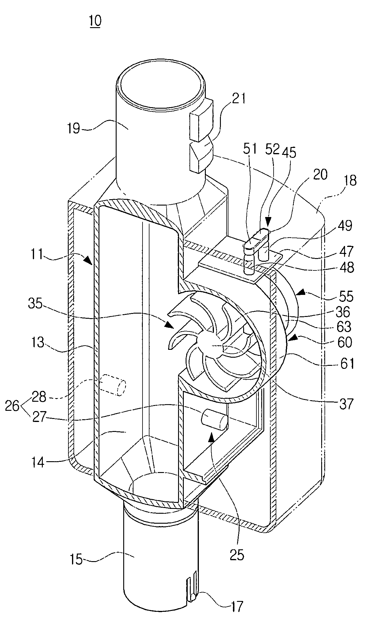
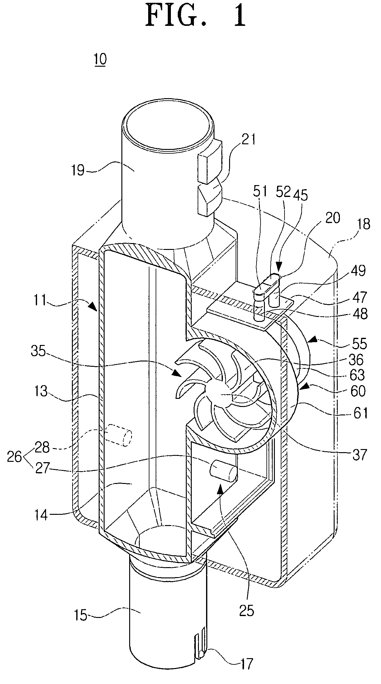
The present invention provides a dust sensing unit for a vacuum cleaner that can automatically detect if there is dust or dirt on a surface and inform the user of the detected result without using an external battery. The unit is modularized, easy to replace, and reduces maintenance costs. It includes a rotating part that is isolated from dust or dirt of the air flowing passage, preventing failure of the rotating part and an electric generator. The body of the unit can be detachably disposed between the suction nozzle and an extended tube, between the extended tube and an operating handle, or between a suction hose and the cleaner body. The detecting sensor is an optical sensor with a light-emitting part and a light-receiving part. The lamp part includes a first lamp and a second lamp. The rotating part is an impeller or a muffler part to reduce noises. The dust sensing unit can also include a subsidiary rotation driving-passage part to draw in external air and rotate the rotating part.

Problems solved by technology

However, the user can not easily perceive whether there is dust or dirt on the surface to be cleaned in a cleaning area soiled with relatively minute dust.
However, since the dust sensing apparatus as described above is usually operated by a separate battery, there is a problem in that the battery should be charged with electricity or replaced with a new one if it is consumed.

Method used


Image

  • Dust sensing unit for use in vacuum cleaner
  • Dust sensing unit for use in vacuum cleaner
  • Dust sensing unit for use in vacuum cleaner

Examples


Embodiment Construction

[0035]Hereinafter, a dust sensing unit for use in a vacuum cleaner according to exemplary embodiments of the present disclosure will now be described in greater detail with reference to the accompanying drawing figures.

[0036]FIG. 11 is a perspective view exemplifying an example of a vacuum cleaner 100 to which a dust sensing unit 10 according to a first exemplary embodiment of the present disclosure is applied

[0037]Referring to FIG. 11, the vacuum cleaner 100 includes a suction nozzle 110, a telescopically extended tube 120, an operating handle 130, a dust sensing unit 10, a suction hose 140, and a cleaner body 150. The suction nozzle 110 draws in air laden with dust or dirt. The extended tube 120 is connected to the suction nozzle 110. The dust sensing unit 10 is installed between the operating handle 130 and the extended tube 120. The suction hose 140 is connected is connected to the operating handle 130. The cleaner body 150 is connected to the suction hose 140 and is divided int...


PUM


Abstract

A dust sensing unit for use in a vacuum cleaner, which can detect whether there is dust or dirt on a surface to be cleaned and inform a user of the detected result in cleaning, is disclosed. The dust sensing unit includes a body having an air flowing passage therein to move air laden with dust or dirt drawn in through a suction nozzle, a detecting sensor disposed on the air flowing passage to detect whether the dust or dirt is passing through the air flowing passage, a lamp part to operate according to a signal outputted from the detecting sensor, a rotating part disposed to the body to rotate by air flowing through the air flowing passage, and an electric generator rotated by the rotating part to generate an electric power.

Description

CROSS-REFERENCE TO RELATED APPLICATIONS[0001]This application claims the benefit under 35 U.S.C. § 119(a) from Korean Patent Application No. 10-2007-35434, filed on Apr. 11, 2007, in the Korean Intellectual Property Office, the entire disclosure of which is incorporated herein by reference.BACKGROUND OF THE INVENTION[0002]1. Field of the Invention[0003]The present disclosure relates to a vacuum cleaner. More particularly, the present disclosure relates to a dust sensing unit for use in a vacuum cleaner, which can detect whether there is dust or dirt on a surface to be cleaned and inform a user of the detected result.[0004]2. Description of the Related Art[0005]Generally, in cleaning, a vacuum cleaner generates a strong suction force by using a suction motor, so that it draws in dust or dirt from a surface to be cleaned thus to clean the surface to be cleaned. Accordingly, the vacuum cleaner is very usefully in cleaning dust or dirt adhered to a surface to be cleaned, such as a carpe...

Claims


Application Information

Patent Timeline
Patent Type & Authority Patents(United States)
IPC IPC(8): A47L9/28
CPCA47L9/19A47L9/248A47L9/2857A47L9/2868A47L9/2815Y02B40/82Y02B40/00A47L9/00A47L9/28
Inventor OH, JANG-KEUNKIM, MIN-HALEE, JIN-GONHAN, JUNG-GYUNCHA, SEUNG-YONG
Owner INTELLECTUAL DISCOVERY CO LTD
Learn More