Gravity gradiometer

a gravity gradiometer and gravity field technology, applied in the field of gravity gradiometers, can solve problems such as significant noise in measurement signals or incorrect measurements mad

Active Publication Date: 2009-07-21
TECH RESOURCES PTY LTD
View PDF96 Cites 18 Cited by
  • Summary
  • Abstract
  • Description
  • Claims
  • Application Information

AI Technical Summary

Benefits of technology

[0008]The object of the invention is to provide a gravity gradiometer in which the internal super-conducting circuitry of the gradiometer is protected from RF interference produced by outside sources.
[0018]Thus, the super-conducting componentry within the Dewar is protected from RF interference by the relay, which needs to be closed in order to enable signals to be passed through the connector and also by the three terminal cap and feed through filter, thereby preventing, or at least substantially reducing, any RF interference which passes from leads external of the Dewar to super-conducting componentry within the Dewar.

Problems solved by technology

Because of the super-conducting nature of the circuitry, the internal circuitry must be protected from RF interference from outside sources, such as telephone and television signals, etc. which result in currents passing from the external circuitry into the internal super-conducting circuitry which can result in incorrect measurements being made or significant noise in the measurement signals.

Method used


Image

  • Gravity gradiometer
  • Gravity gradiometer
  • Gravity gradiometer

Examples


Embodiment Construction

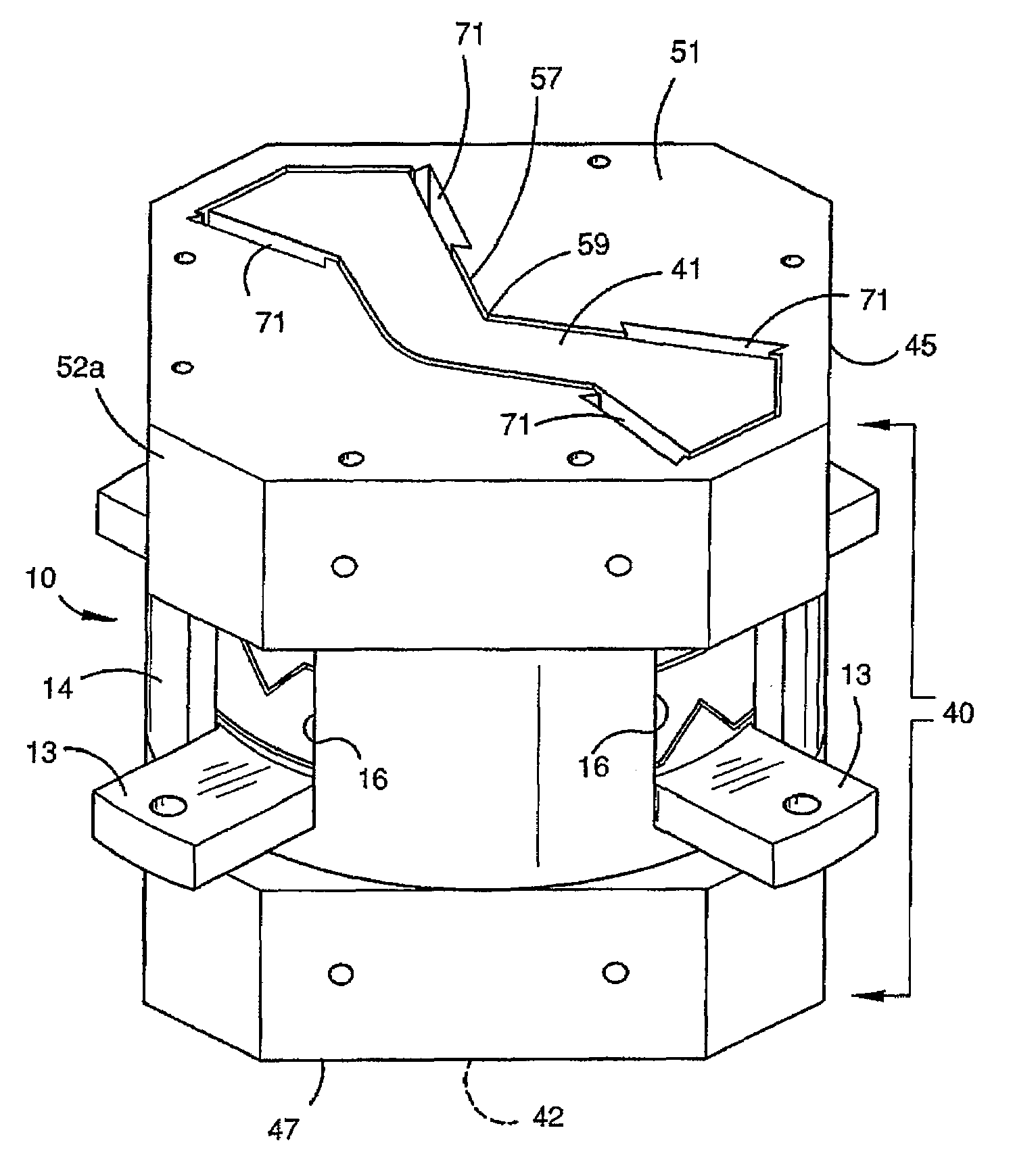
[0078]FIG. 1 is a schematic view of a gravity gradiometer according to one embodiment of the invention.

[0079]The gradiometer shown in FIG. 1 comprises a double walled Dewar 1 which is supported in an external platform 2. The external platform 2 enables adjustment of the Dewar and therefore the contents of the Dewar about three orthogonal axes. The external platform 2 is generally known and its adjustment by suitable motors or the like is also known. Thus, a detailed description will not be provided.

[0080]A vacuum canister 3 is provided in the Dewar and the Dewar is supplied with liquid gas such as liquid helium He so that the gradiometer can operate at cryogenic temperature. The Dewar 1 is closed by an end plate 4 which includes connectors 5a for connecting electrical leads (not shown) to external components (not shown).

[0081]The canister 3 is closed by an end plate 9 which includes connectors 5b for connecting electric leads (not shown) to the connectors 5a. The gradiometer has a m...


PUM


Abstract

A gravity gradiometer is disclosed which has a pair of sensor bars 41, 42 mounted in housings 43 and 45. Transducers 71 are located adjacent the bars for measuring movement of the bars in response to the gravity gradient tensor. Signals from the transducers are supplied to a SQUID device 367 for processing the signals. A connector is supplied for connecting the circuitry to external equipment which comprises a container 560 having a feed through filter 564, a three terminal cap 565, a relay 566 and an output terminal. The output terminal is connected to further RF attenuation which comprises a second connector 5b having parallel inductors and resistors.

Description

FIELD OF THE INVENTION[0001]This invention relates to a gravity gradiometer, and in particular, but not exclusively, to a gravity gradiometer for airborne use. The invention has particular application for measuring diagonal and off-diagonal components of the gravitational gradient tensor.BACKGROUND OF THE INVENTION[0002]A gravity gradiometer is disclosed in our International Patent Application No. PCT / AU2006 / 001269 and several concurrently filed applications. The content of International Patent Application No. PCT / AU2006 / 001269 is incorporated into this specification by this reference.[0003]Gravimeters are widely used in geological exploration to measure the first derivatives of the earth's gravitational field. Whilst some advances have been made in developing gravimeters which can measure the first derivatives of the earth's gravitational field because of the difficulty in distinguishing spatial variations of the field from temporal fluctuations of accelerations of a moving vehicle...

Claims


Application Information

Patent Timeline
Patent Type & Authority Patents(United States)
IPC IPC(8): G01C9/14G01V7/16
CPCG01V7/04
Inventor VAN KANN, FRANK JOACHIMWINTERFLOOD, JOHN
Owner TECH RESOURCES PTY LTD
Why Eureka
Try Eureka