Liquid crystal display

a liquid crystal display and display technology, applied in non-linear optics, instruments, optics, etc., can solve problems such as poor side visibility, and achieve the effect of reducing light leakage through the side of the display and not lowering the contrast ratio on the sid

Active Publication Date: 2016-12-13
TCL CHINA STAR OPTOELECTRONICS TECH CO LTD
View PDF4 Cites 0 Cited by
  • Summary
  • Abstract
  • Description
  • Claims
  • Application Information

AI Technical Summary

Benefits of technology

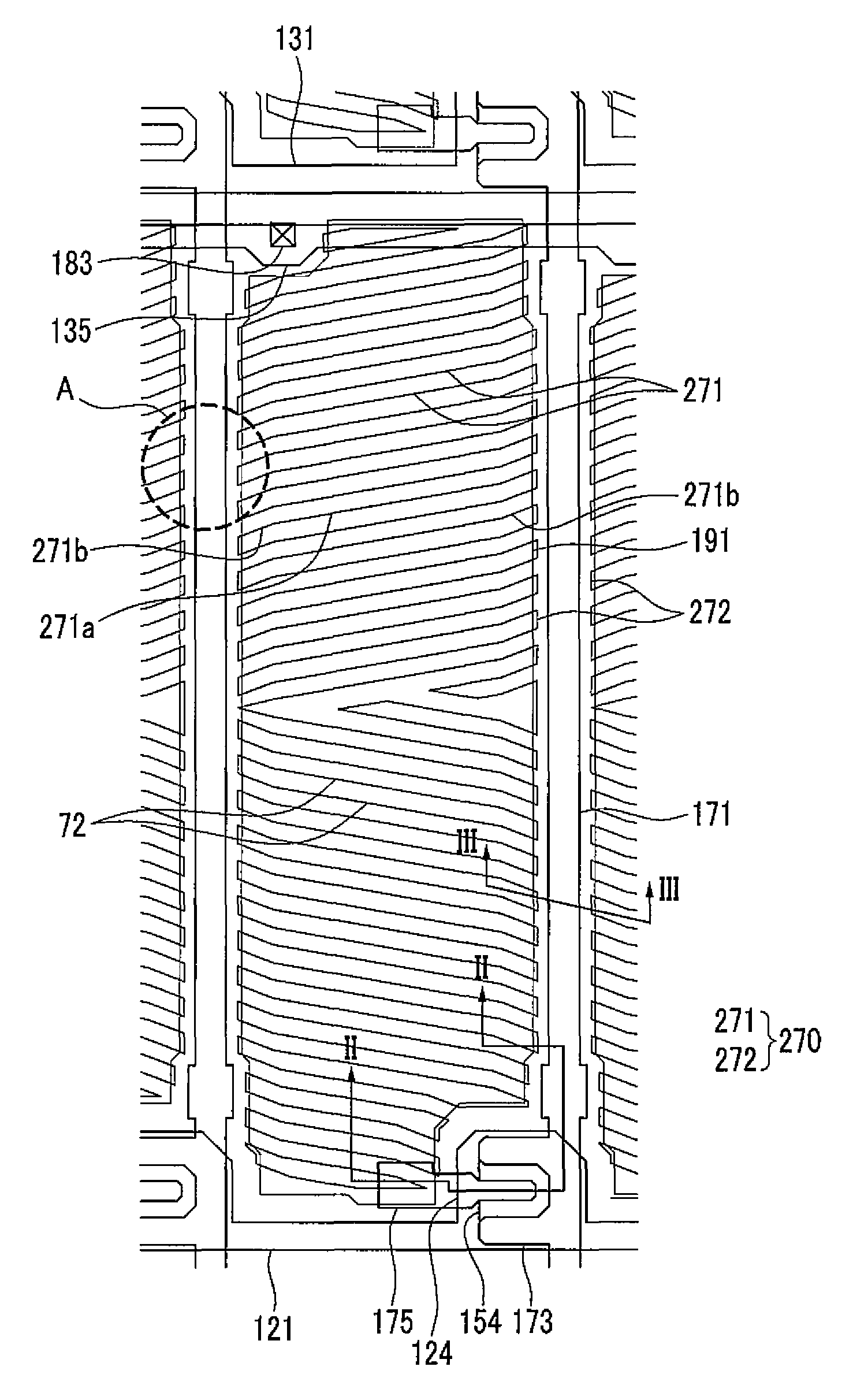
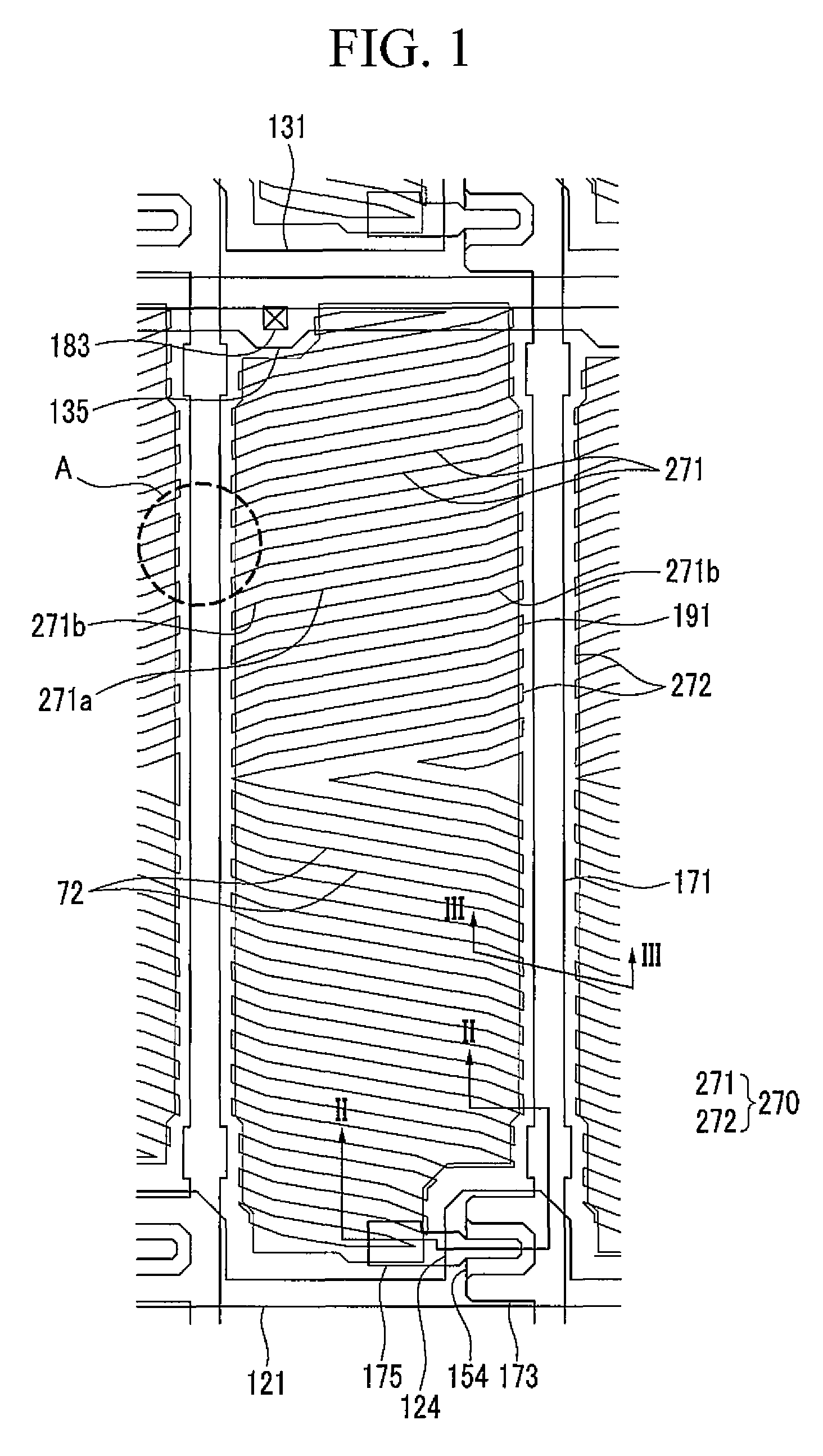
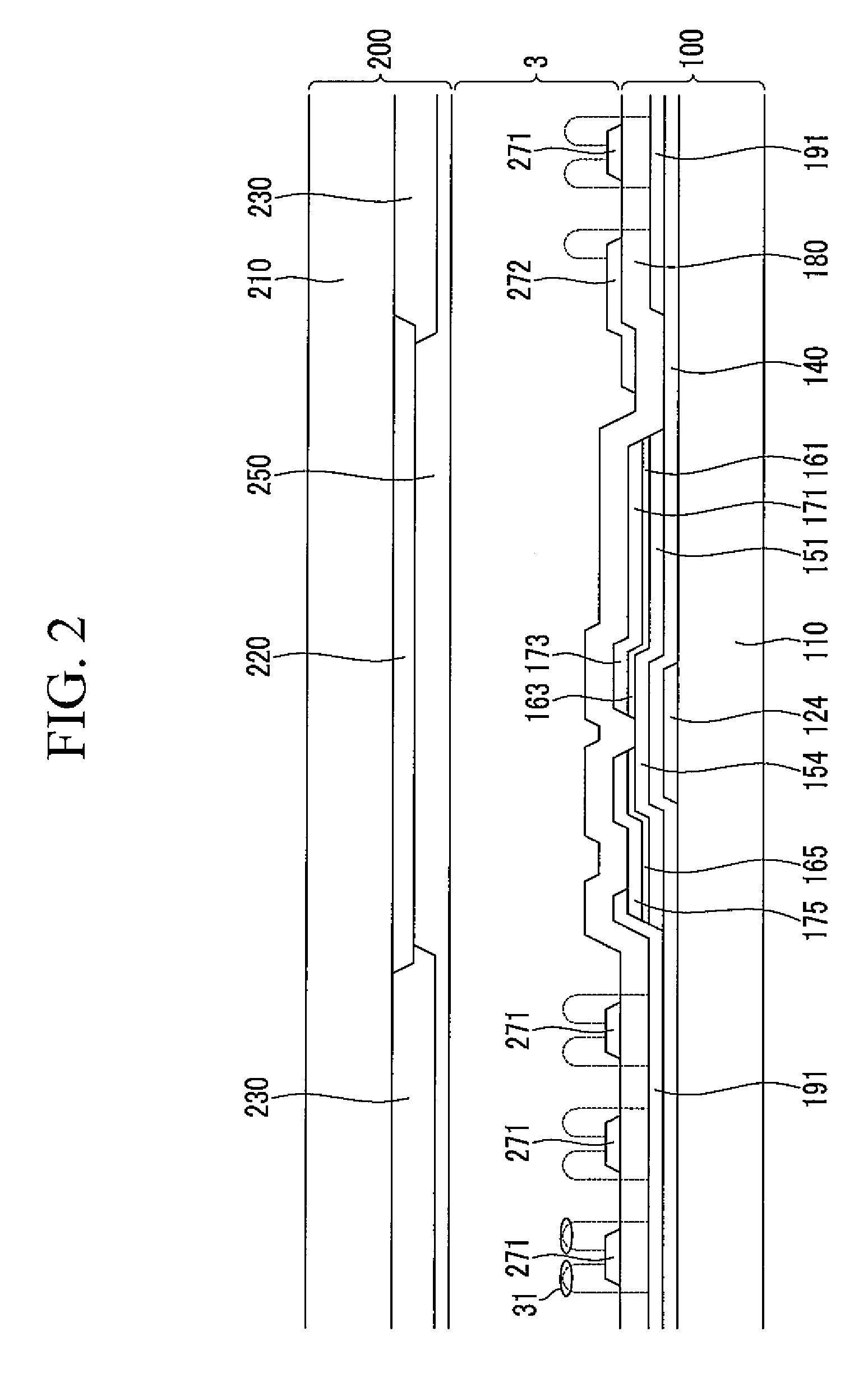
[0009]An aspect of an embodiment of the present invention is directed toward a liquid crystal display for reducing (e.g., preventing) light leakage through a side of the display without lowering a contrast ratio on its side, the liquid crystal display being formed with a pixel electrode and a common electrode on a substrate.
[0021]Accordingly, in the liquid crystal display according to an example embodiment of the present invention, the contrast ratio on the side is not lowered and light leakage through the side of the display is reduced (e.g., prevented), the liquid crystal display being formed with the pixel electrode and the common electrode on a single substrate.

Problems solved by technology

The liquid crystal display has a merit in that the liquid crystal display is easily manufactured to be thin, but has a drawback in that side visibility is poor compared to front visibility, and as a result, in order to overcome the drawback, various methods of arranging and driving the liquid crystal have been developed.

Method used


Image

  • Liquid crystal display
  • Liquid crystal display
  • Liquid crystal display

Examples


Embodiment Construction

[0029]The present invention will be described more fully hereinafter with reference to the accompanying drawings, in which example embodiments of the invention are shown. As those skilled in the art would realize, the described embodiments may be modified in various different ways, all without departing from the spirit or scope of the present invention.

[0030]In the drawings, the thickness of layers, films, panels, regions, etc., are exaggerated for clarity. Like reference numerals designate like elements throughout the specification. It will be understood that when an element, such as a layer, film, region, or substrate, is referred to as being “on” another element, it may be directly on the other element or intervening elements may also be present. In contrast, when an element is referred to as being “directly on” another element, there are no intervening elements present.

[0031]It will be understood that, although the terms “first”, “second”, “third”, etc., may be used herein to de...


PUM


Abstract

A liquid crystal display including a first substrate and a second substrate facing the first substrate, a gate line and a data line on the first substrate, a thin film transistor coupled to the gate line and the data line, a pixel electrode coupled to the thin film transistor, and a common electrode overlapping the pixel electrode with an insulating layer therebetween, and including a plurality of branch electrodes and a connector coupling the branch electrodes, the common electrode overlapping the data line and extending in parallel with the data line, wherein a width of the connector of the common electrode is about 8.0 μm to about 13.5 μm.

Description

CROSS-REFERENCE TO RELATED APPLICATION[0001]This application claims priority to and the benefit of Korean Patent Application No. 10-2014-0076074, filed in the Korean Intellectual Property Office on Jun. 20, 2014, the entire content of which is incorporated herein by reference.BACKGROUND[0002]1. Field[0003]Aspects of one or more embodiments of the present invention relate to a liquid crystal display.[0004]2. Description of the Related Art[0005]A liquid crystal display is currently one of the most widely used (or utilized) flat panel displays, and is a display device that adjusts an amount of transmitted light by applying a voltage to an electrode and rearranges liquid crystal molecules of a liquid crystal layer.[0006]The liquid crystal display has a merit in that the liquid crystal display is easily manufactured to be thin, but has a drawback in that side visibility is poor compared to front visibility, and as a result, in order to overcome the drawback, various methods of arranging ...

Claims


Application Information

Patent Timeline
Patent Type & Authority Patents(United States)
IPC IPC(8): G02F1/136G02F1/1343
CPCG02F1/134309G02F2001/134372G02F1/134372
Inventor LEE, SEUNG JAE
Owner TCL CHINA STAR OPTOELECTRONICS TECH CO LTD
Why Eureka
Try Eureka