
Dryer, and motor mounting structure of the same

a technology of motor and mounting structure, which is applied in the field of dryers, can solve the problems of cushion separation from the driving shaft, difficult to repair the motor, and difficulty in mounting and dismounting the motor, and achieve the effects of convenient repair, improved motor operation reliability, and convenient mounting and dismounting

Active Publication Date: 2009-07-21
PROCTER & GAMBLE CO +1
View PDF9 Cites 11 Cited by
  • Summary
  • Abstract
  • Description
  • Claims
  • Application Information

AI Technical Summary

Benefits of technology

The present invention provides a dryer and a motor mounting structure that overcome limitations and disadvantages of the related art. The dryer has a motor mounting structure that allows for easy mounting and dismounting of the motor, as well as convenient repair of the motor's periphery. The motor mounting structure also securely locates and supports a cushion at the motor's periphery to improve its operational reliability. The motor mounting structure includes a base, a motor supporter, and guide parts that facilitate the mounting of the motor shaft. The motor mounting structure also includes a circular shaped cushion and guide parts that have a corresponding shape to ensure stability and reliability of the motor mounting.

Problems solved by technology

Alternatively, a conventional motor mounting structure has a drawback in that since the motor is disposed in a larger space, it is difficult to mount and dismount the motor.
Further, the conventional motor mounting structure has a drawback in that it is difficult to repair the motor.
Accordingly, the conventional motor mounting structure has a drawback in that in case where the vibration is continuously applied to the cushion, the cushion is separated from the driving shaft.

Method used


Image

  • Dryer, and motor mounting structure of the same
  • Dryer, and motor mounting structure of the same
  • Dryer, and motor mounting structure of the same

Examples


Embodiment Construction

[0027]Reference will now be made in detail to the preferred embodiments of the present invention, examples of which are illustrated in the accompanying drawings. Wherever possible, the same reference numbers will be used throughout the drawings to refer to the same or like parts.

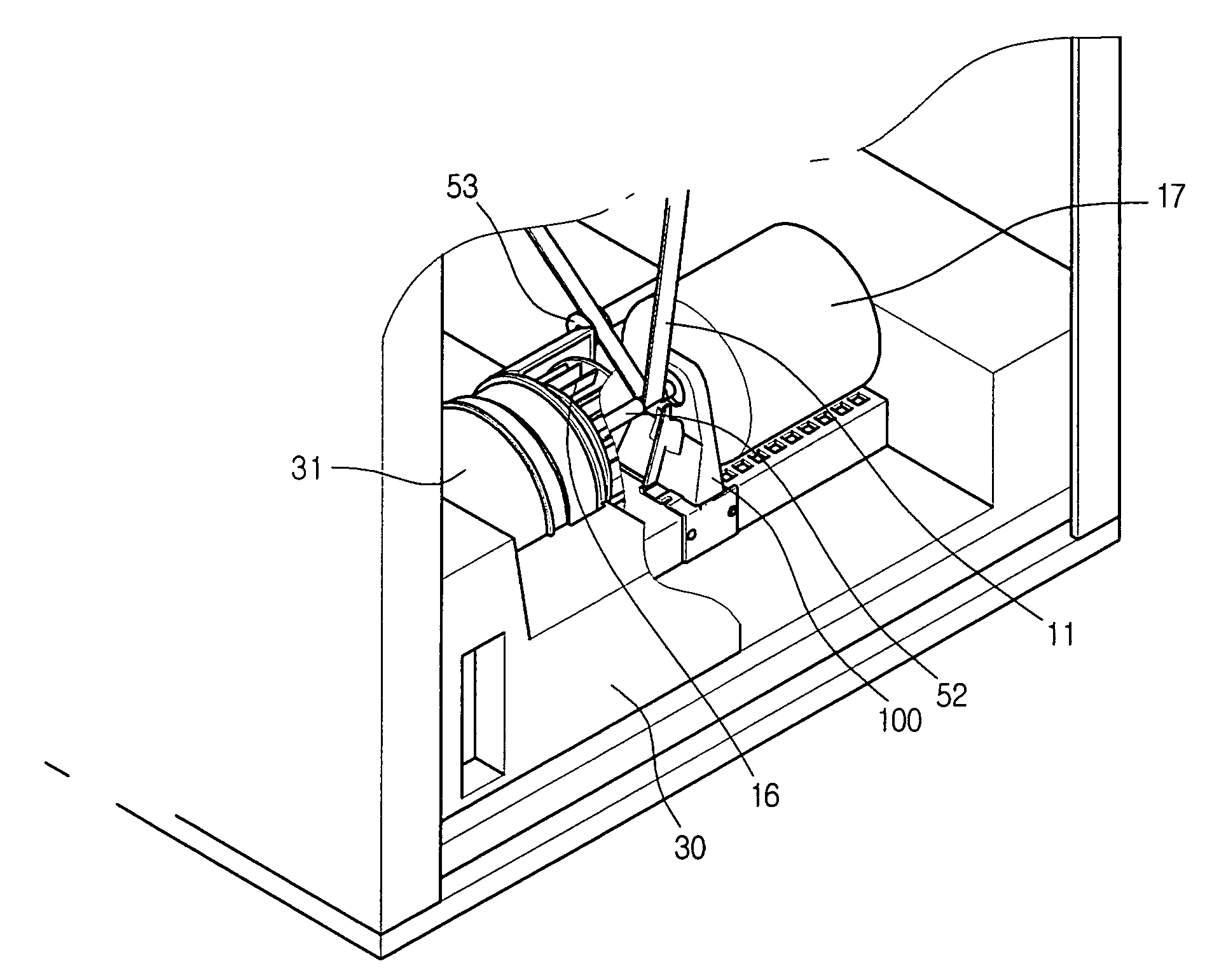
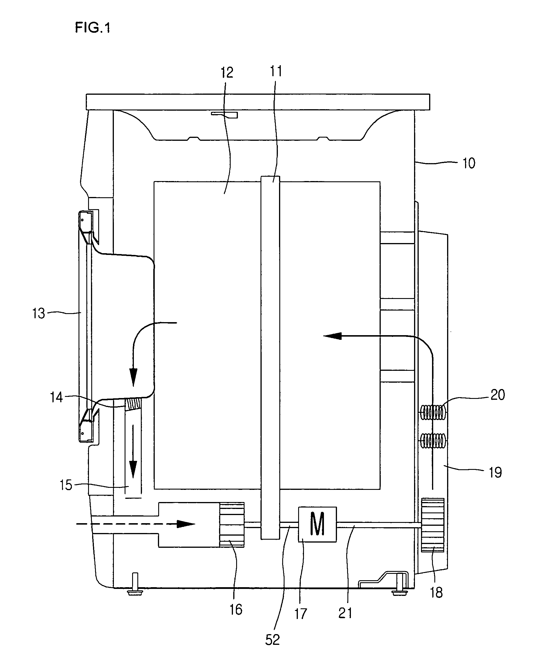
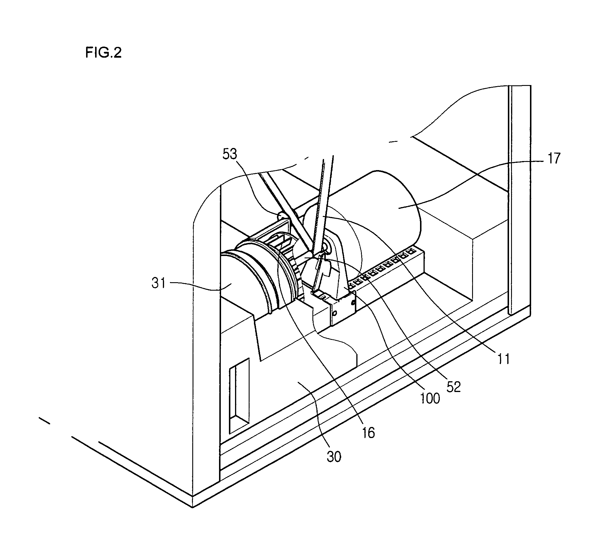
[0028]FIG. 1 is a schematic sectional view illustrating a drum dryer according to the present invention, and FIG. 2 is an enlarged perspective view illustrating a periphery of a motor according to the present invention.

[0029]Referring to FIGS. 1 and 2, the condenser-type drum dryer includes a cabinet 10 providing an exterior appearance; a cylindrical drum 12 disposed inside of the cabinet 10; a door for opening and closing the drum 12; and a belt 11 wound around the drum 12.

[0030]Further, the dryer includes a cooling fan side motor shaft 52 connected with the belt 11; a drying fan side motor shaft 21 connected with a motor 17 at an opposite of the cooling fan side motor shaft 52; the motor 17 connected with ...


PUM


Abstract

A dryer and a motor mounting structure of the same are provided. The dryer includes: a cabinet; a drum housed inside of the cabinet; a motor for providing a driving force to the drum; a belt for connecting a driving shaft of the motor with the drum; a base disposed at a lower side of the drum; a motor supporter having a pass-through part, which is disposed at its one side and supports the driving shaft; a cushion provided between the driving shaft and the motor supporter; a guide rib provided at the base; and a guide rib inserting part provided at the motor supporter to have a corresponding shape of the guide rib, such that the motor supporter is slid and mounted on the base.

Description

BACKGROUND OF THE INVENTION[0001]1. Field of the Invention[0002]The present invention relates to a dryer, and more particularly, to a motor mounting structure for firmly supporting a motor when a dryer is operated. Much more particularly, the present invention relates to a dryer and a motor mounting structure of the same in which a motor can be conveniently mounted and dismounted, and parts are not destroyed when the motor is operated.[0003]2. Description of the Related Art[0004]Dryer sends hot air, which is generated by an electric heater, a gas combustion device or the like, inside of a drum to eliminate remnant moisture from a target object such as clothing, thereby drying the target clothing.[0005]The dryer includes a drum rotating with the clothing housed therein; a motor for rotating the drum; a heater for heating the air; a circulation fan for circulating the air; and a passage structure for flowing the air.[0006]Further, the dryer is operated in such a manner that a belt is ...

Claims


Application Information

Patent Timeline
Patent Type & Authority Patents(United States)
IPC IPC(8): F26B19/00F26B11/02D06F37/20D06F58/08H02K5/00
CPCH02K5/00D06F58/08
Inventor DOH, YOUNG JIN
Owner PROCTER & GAMBLE CO
Learn More