Actuating device with at least one actuating arm

Active Publication Date: 2009-07-21
JULIUS BLUM GMBH
View PDF17 Cites 22 Cited by
  • Summary
  • Abstract
  • Description
  • Claims
  • Application Information

AI Technical Summary

Benefits of technology

[0012]By means of the braking or locking device, the swing speed of the actuating arm can be reduced and/or the actuating arm can be arrested temporarily in its pivoting position. The swing speed of the actuating arm can thereby be gradually reduced or abruptly decelerated to zero.
[0013]One preferred embodiment of the invention provides for the braking or stopping device to comprise a mechanical clutch device. In this connection, it can be advantageous if the mechanical clutch device comprises a centrifugal clutch. Thereby a first—preferably spring-loaded—clutch member can be formed or arranged onto the actuating arm, wherein this first clutch member is arranged on the bearing axis of the actuating arm with a freedom of radial movement on the bearing axis of the actuating arm and which forms part of the centrifugal clutch. If the swing speed of the actuating arm exceeds the threshold value, then the first clutch member is pressed radially outwards due to the operative centrifugal force. In this context, it is advantageous if the first clutch member comprises at least one stopping tooth which can be applied in one position to a second clutch member, preferably an internally geared ring. As an alternative to this

Problems solved by technology

Critical torques arise during the transporting, fitting or changing of the flap since the charging spring device accelerates the relatively light actuating arm like a bullet

Method used


Image

  • Actuating device with at least one actuating arm
  • Actuating device with at least one actuating arm
  • Actuating device with at least one actuating arm

Examples


Embodiment Construction

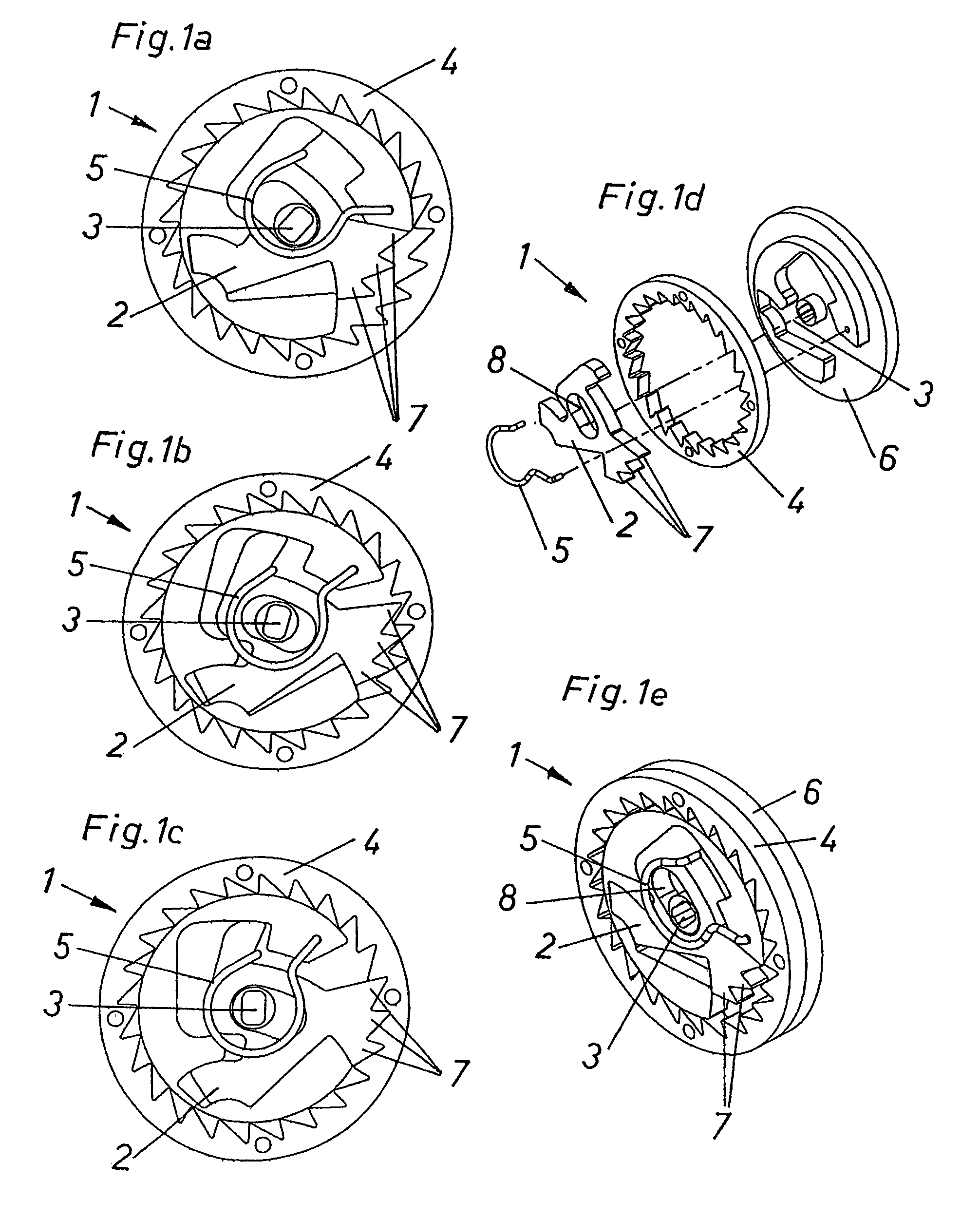
[0033]FIGS. 1a-1e show various views of an example of a braking or stopping device 1 according to the invention. FIG. 1a-1c show various temporal sequences of the engaging process if a threshold value of the swing speed of an actuating arm—which is not shown for reasons of clarity—is exceeded. FIG. 1a shows the braking or stopping device 1 in the non-geared state, FIG. 1b shows the moment of the snap-in procedure and FIG. 1c shows the at rest status. As can be seen in particular from the representation of the explosion in FIG. 1d, the braking or stopping device 1 is designed as a ratched locking mechanism with a ratchet gear. A receiving member 6 is fitted coaxially to the bearing axis 3 of the actuating arm. The receiving member 6 is constructed so that the second clutch member 4 can be pushed onto the latter. In the example shown, the second clutch member 4 is constructed as an internally toothed ring. The first clutch member 2 forms the counter-piece to the internally toothed rin...


PUM


Abstract

The invention relates to an actuating device for moving a flap of a piece of furniture, including at least one actuating arm for moving the flap, a base member on which the actuating arm is pivotally arranged, and a spring device able to act upon the actuating arm. An assembly securing device for the vacant actuating arm, which has not yet been fitted with a flap, includes a braking device which limits the opening speed of the vacant actuating arm.

Description

[0001]This application is a continuation of International application No. PCT / AT2005 / 000522, filed Dec. 22, 2005.BACKGROUND OF THE INVENTION[0002]The present invention relates to an actuating device with at least one actuating arm, designed in particular to operate a flap of a piece of furniture, having a base member on which the actuating arm is pivotally located and a spring device to act upon the actuating arm.[0003]Actuating devices of this type are generally attached onto a lateral wall of a piece of furniture and serve to move the flap connected to the actuating arm from the open to the closed position or vice-versa. According to the size and weight of the furniture flap, the actuating devices are provided with a spring device which moves the actuating arm with extremely high prestress forces so that even heavy flaps on items of furniture can be moved. Critical torques arise during the transporting, fitting or changing of the flap since the charging spring device accelerates t...

Claims


Application Information

Patent Timeline
IPC IPC(8): E05F3/00E05D15/26E05F1/10
CPCE05F1/1058E05F5/00E05Y2201/21E05Y2201/242E05Y2201/26Y10T16/61E05Y2900/20E05Y2600/00E05Y2800/40E05Y2201/224Y10T16/54E05Y2201/266
Inventor DUBACH, FREDIOMANN, CHRISTIAN
Owner JULIUS BLUM GMBH
Why Eureka
Try Eureka