
Cap structure for beverage container

a beverage container and cap structure technology, applied in the direction of caps, liquid handling, closures using stoppers, etc., can solve the problems of long time-consuming and bad taste, and achieve the effects of convenient sanitary and safety, improved taste, and simple operation

Active Publication Date: 2009-07-21
NIPPONKOATSUDENKI +1
View PDF20 Cites 31 Cited by
  • Summary
  • Abstract
  • Description
  • Claims
  • Application Information

AI Technical Summary

Benefits of technology

"The present invention relates to an improved beverage container in which a fine-powdery mixture and a drinking water are separately stored and can be mixed just before drinking. The container has a cap structure that allows for easy mixing of the ingredients and is designed to prevent the mixture from becoming stale or losing flavor during storage. The cap structure includes a removable cap that can be screwed onto the container body and a container disposed inside the cap for storing the mixture. The cap has a small cylindrical part that is bonded to the container body and a mechanically weak portion at the bottom of the container for easy opening. The cap can be opened and closed with a simple operation to mix the ingredients and drink the beverage. The invention solves the problem of small space for dropping the mixture and ensures that the mixture can be thoroughly mixed without leaving any residue."

Problems solved by technology

It takes a long time to pass these beverages to consumers and there is a problem that deliciousness becomes bad by aged deterioration during storing.

Method used


Image

  • Cap structure for beverage container
  • Cap structure for beverage container
  • Cap structure for beverage container

Examples


example 1

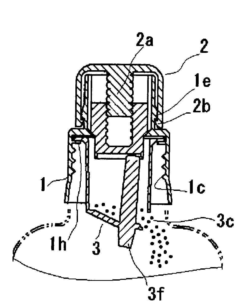
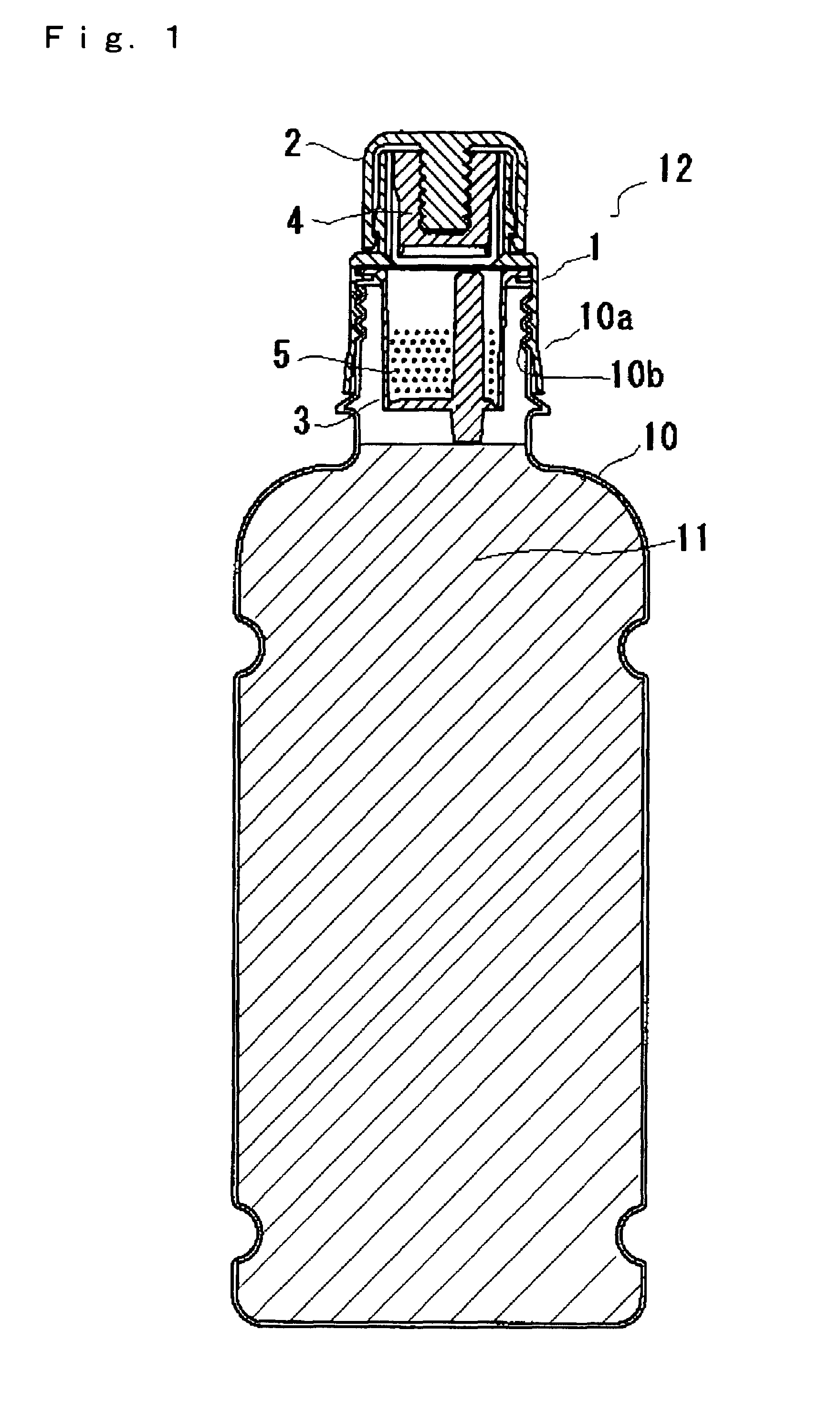
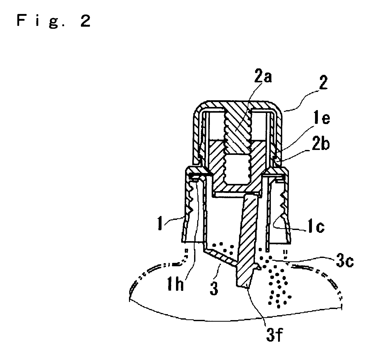
[0073]The cap (1) consists of a cap (1) having a shape in which a small diameter cylindrical part (1a) is bonded to the upper side of a large diameter cylindrical part (1b), an openable lid (2) attached so as to cover the small diameter cylindrical part (1a) of the cap (1), a pressing cap (4) which is disposed in the small diameter cylindrical part (1a) and is capable of moving downward at the same time of rotation of the openable lid (2), and a container (3) which has a powdery tea (5) setting in the large diameter cylindrical part (1b) and under the pressing cap (4), shown in FIGS. 1 and 2.

[0074]The cap (1) shown in FIG. 3 is made of a synthetic resin, namely polypropylene resin (PP) and has a shape wherein a small diameter cylindrical part (1a) is bonded to the upper side of a large diameter cylindrical part (1b), and a threaded part (1c) is disposed at an inner circumferential surface of the large diameter cylindrical part (1b) for removably screwing onto a threaded part (10b) f...

example 2

[0101]In the following, Example 2 is described focusing on differences from Example using FIGS. 6 and 7.

[0102]The cap (7) consists of a cap (7) having a shape in which a small diameter cylindrical part (7a) is bonded to the upper side of a large diameter cylindrical part (7b), an openable lid (6) which has a cylindrical shape, is communicated downward while attaching so as to cover the small diameter cylindrical part (7a) of the cap (7) and has a projected portion (6a) at the central, and a container (3) which is disposed inside of the large diameter cylindrical part (7b) of the cap (7) same as the case in Example 1.

[0103]The description on the construction of the container (3) is omitted because it is the same as the case in Example 1. In addition, since the container (3) is fixed by a pawl portion (7f) disposed in the cap in the same manner as Example 1, the container (3) can be easily removed.

[0104]The cap (7) is made of a synthetic resin, namely polypropylene resin (PP) and has ...


PUM


Abstract

A beverage container enabling a flavored tea to be tasted is provided when a powdered tea stored normally in a sealed container of a cap and a drinking water in a body are blended. The cap is provided on the body. When the cap is rotated, a force is imparted on a pressing rod extending from the bottom surface of the container. This force causes a mechanically weak portion in the bottom of the container to break, thus allowing a mixture to fall from the container into the drinking water.

Description

BACKGROUND OF THE INVENTION[0001]1. Field of the Invention[0002]The present invention relates to an improved beverage container in which a fine-powdery mixture and a drinking water are stored separately, and they are subjected to mixing for drinking the beverage.[0003]2. Related Art[0004]Conventionally, a beverage such as tea, coffee and juice is sold at a store or via an automatic vending machine, which is plugged into a beverage container such as a can, a bottle and a plastic bottle of PET. It takes a long time to pass these beverages to consumers and there is a problem that deliciousness becomes bad by aged deterioration during storing. Therefore, a beverage container is proposed, which is an easy-to-drink container capable of tasting the flavor of freshly brewed tea by blending a seasoning material such as powdered tea, and a drinking water just before drinking (for example, in Patent Document 1).[0005]The invention described in JP-A 2003-72822 by the present applicant, for exam...

Claims


Application Information

Patent Timeline
Patent Type & Authority Patents(United States)
IPC IPC(8): B65D51/28B65D81/32
CPCB65D81/3222B65D51/2842Y10S215/08B65D25/08B65D51/28B65D81/32
Inventor YORITA, KATSUHIKO
Owner NIPPONKOATSUDENKI
Learn More