Electronic enclosure with continuous ground contact surface

a ground contact surface and electronic enclosure technology, applied in the direction of electrical apparatus casings/cabinets/drawers, coupling device connections, shielding materials, etc., can solve the problems of limiting the electrical continuity between the cover and the cover, affecting the efficiency of the known electronic enclosure, and affecting the repairability of the enclosure, so as to improve the repairability, improve the sealing integrity, and facilitate the dispersion of sealan

Inactive Publication Date: 2009-07-21
RPX CORP
View PDF14 Cites 38 Cited by
  • Summary
  • Abstract
  • Description
  • Claims
  • Application Information

AI Technical Summary

Benefits of technology

[0011]Accordingly, the enclosure for electronic circuitry provides one or more of the following advantages: it eliminates the cover to housing fasteners; it provides one or more continuous ground contact surfaces; it achieves easy sealant dispersion; it improves seal integrity; it improves the repairability of the enclosure; it provides a unique attachment of a cover to a housing to achieve electrical continuity; it provides a complete perimeter adhesive between the housing and the cover; and it is efficient and inexpensive to manufacture.

Problems solved by technology

Known electronic enclosures often are generally not efficient.
The use of separate fasteners to affix the cover to the housing complicates the assembly process of the cover to the housing.
Further, separate fasteners limit the amount of electrical continuity between the cover and the housing.
The arrangement of the fasteners, the cover, and the housing results in difficult dispersion of adhesive between the cover and the housing and does not provide optimal seal integrity.
Repair of an enclosure with four separate fasteners, a housing, a cover, and a seal is difficult.

Method used


Image

  • Electronic enclosure with continuous ground contact surface
  • Electronic enclosure with continuous ground contact surface
  • Electronic enclosure with continuous ground contact surface

Examples


Embodiment Construction

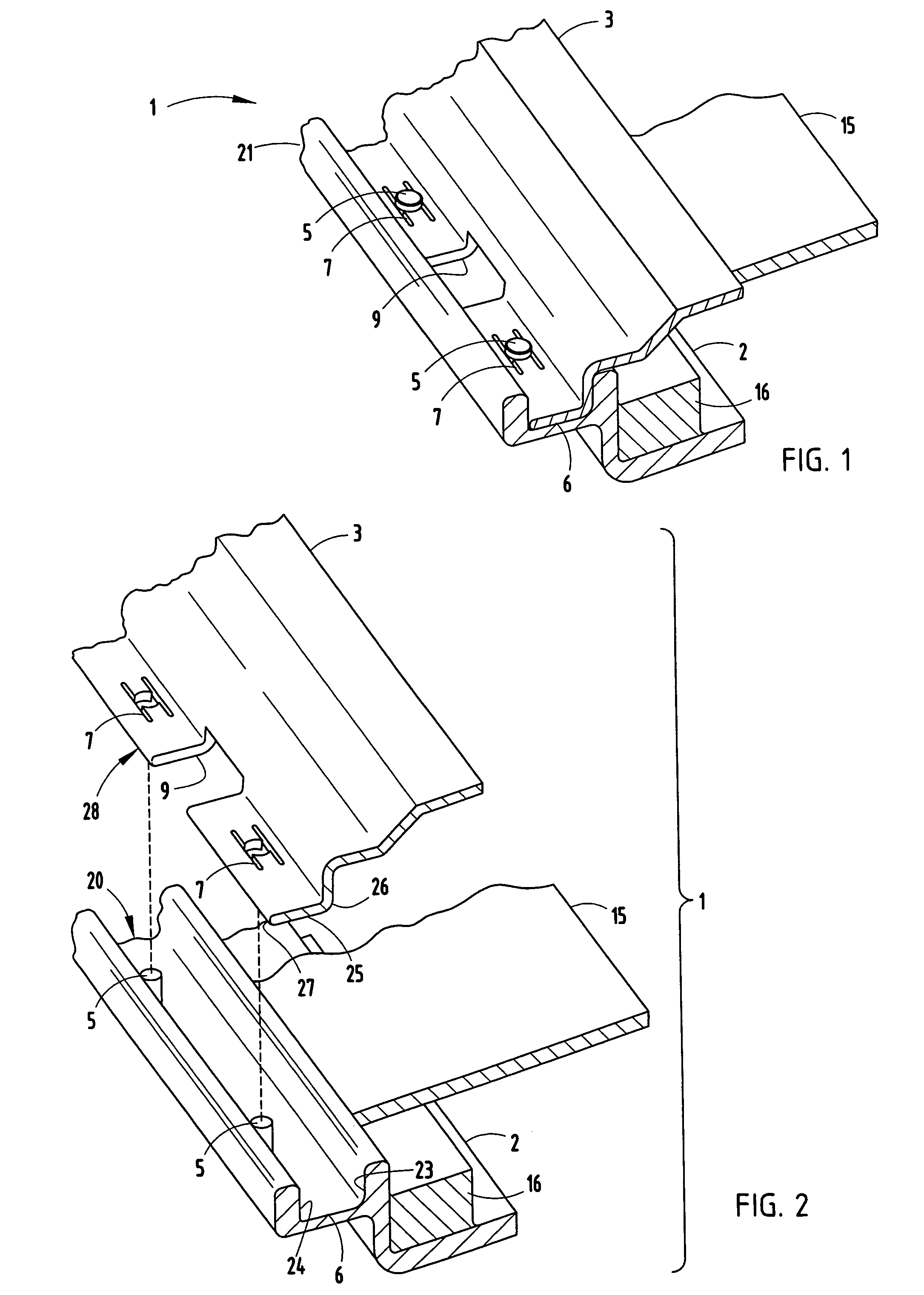
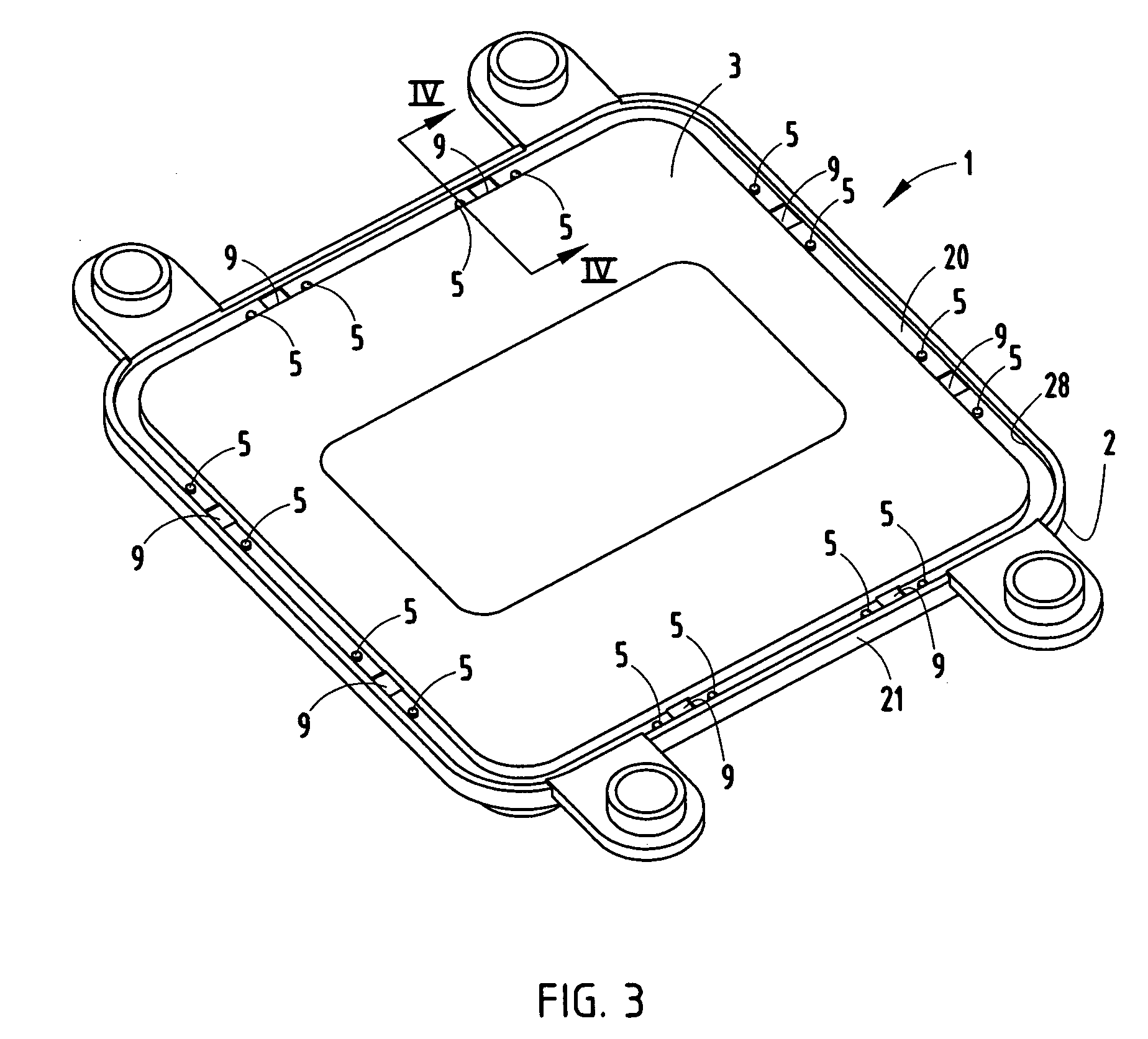
[0023]Referring now to FIGS. 1-3, an electronic enclosure 1 is illustrated that embodies one embodiment with a continuous electrical ground surface. The electronic enclosure 1 may be configured to enclose any variety of electronic circuitry located within the enclosure 1. For example, the electronic enclosure 1 may enclose a circuit board containing electrical circuitry and any of a number of electronic components. The electronic enclosure 1 with continuous ground contact surface may be of a rectangular (e.g., square) or other shape. Also, the electronic enclosure 1 may be used in a variety of applications, including automotive applications.

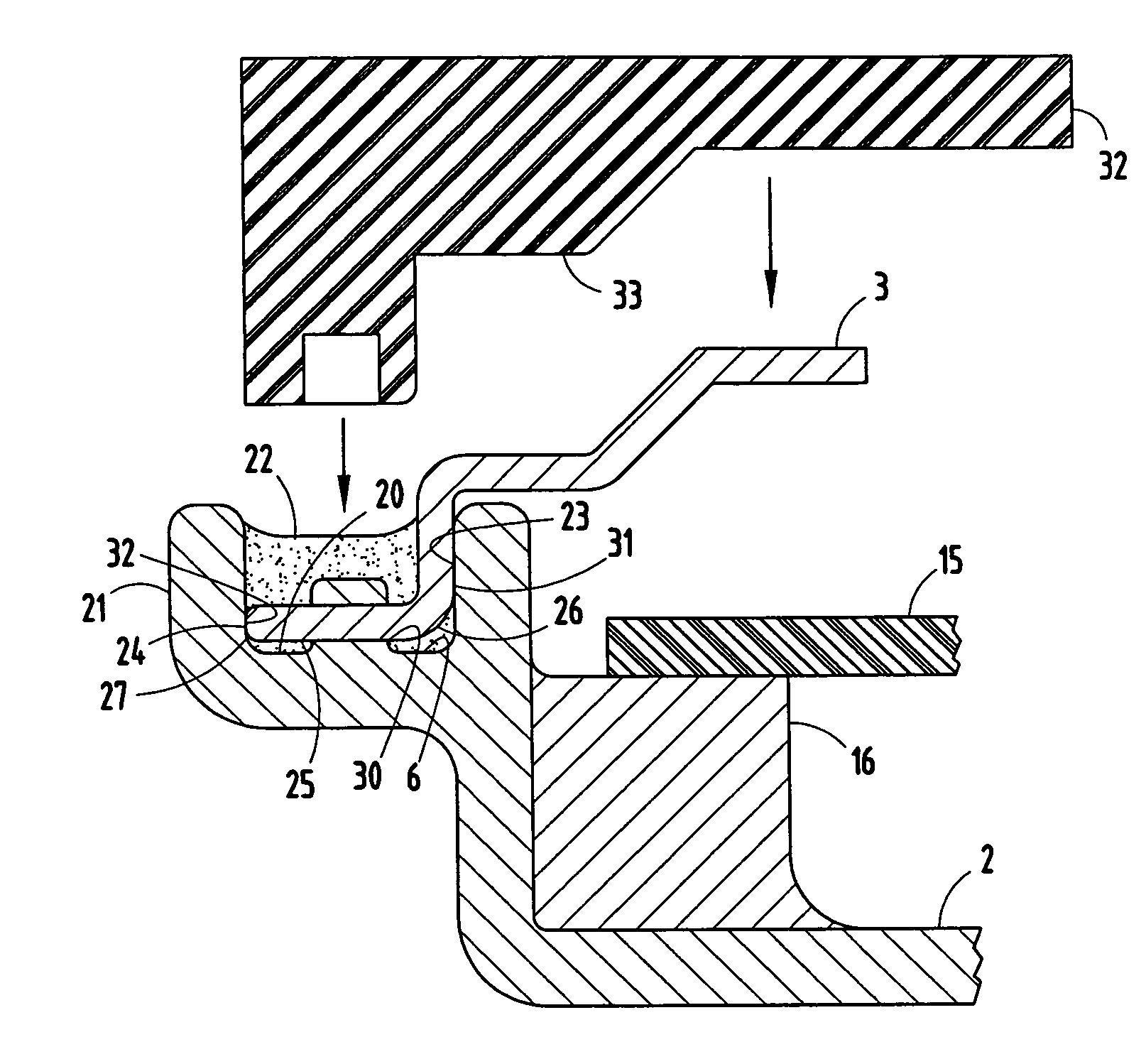
[0024]As seen in FIG. 1, first and a second housing members, referred to as housing 2 and cover 3, respectively, of the electronic enclosure 1 are secured to one another by posts 5 formed in bottom wall 6 of trough 20 of housing 2 and received by slots 7 of cover 3. The housing members 2 and 3 are formed of electrically conductive materials, such...


PUM


Abstract

An enclosure for electronic circuitry is provided which has a first housing member having at least one protrusion formed in a wall and a second housing member having at least one slot for receiving the at least one protrusion and securing the second housing member to the first housing member. The second housing member and the first housing member have one or more continuous electrical ground contact surfaces. The second housing member is secured to the first housing member so that there is an interference fit between the at least one protrusion and at least one slot and so that there are one or more continuous electrical ground contact surfaces between the first housing member and the second housing member. A method of assembling an enclosure for electronic circuitry is provided.

Description

TECHNICAL FIELD[0001]The present invention generally relates to enclosures for electronic circuitry, and more particularly relates to electrical interconnection of the components of enclosures for electronic circuitry.BACKGROUND OF THE INVENTION[0002]Enclosures for electronic circuitry typically include a case or housing, a cover, a seal between the housing and the cover, and fasteners for attaching the cover to the housing. Usually, the housing and cover are made of an electrically conductive material (e.g., metal) and have matching shapes, e.g., a square shape. To assemble a conventional electronics enclosure, adhesive is applied near the perimeter of the housing. The cover is placed on top the adhesive surface. Fasteners are threaded through the cover, adhesive and housing to affix the cover to the housing and to establish electrical interconnection between the cover and the housing. The electrical interconnection at the fasteners provides direct current (DC) and radio frequency ...

Claims


Application Information

Patent Timeline
Patent Type & Authority Patents(United States)
IPC IPC(8): H01R13/502
CPCH05K9/0073H05K5/062
Inventor LAWLYES, DANIEL A.RATELL, JOSEPH M.
Owner RPX CORP
Why Eureka
Try Eureka