
Micro-electro-mechanical transducer having embedded springs

a technology of micro-electromechanical and transducer, which is applied in the direction of mechanical vibration separation, generator/motor, instruments, etc., can solve the problems of high cost, high difficulty in processing, and limitation of the cell size in the design of the cmut,

Active Publication Date: 2009-07-21
KOLO MEDICAL (SUZHOU) CO LTD
View PDF7 Cites 86 Cited by
  • Summary
  • Abstract
  • Description
  • Claims
  • Application Information

AI Technical Summary

Problems solved by technology

This process is fraught with difficulties and high expenses, not to mention the large input impedance mismatch problem presented by such elements to transmit / receiving electronics.
There are drawbacks in the cMUTs of the prior art structures and methods.
Many of these drawbacks relate to the fact that each addressable cMUT element is made of many individual cells and each cell has its cMUT membrane clamped or fixed on edges shared by the adjacent cells.
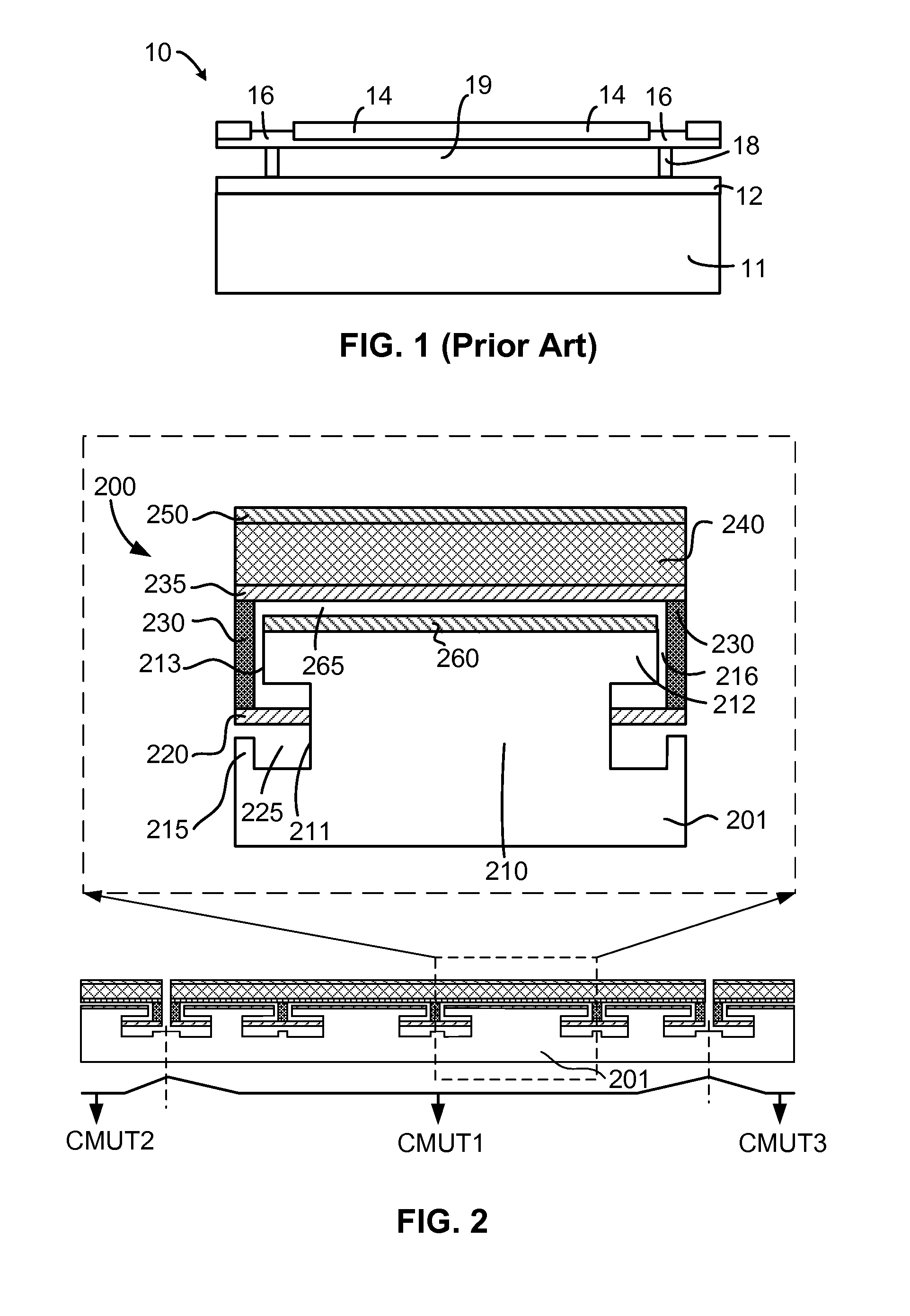
Specifically, there exists a cell limitation in the design of the cMUT showing in FIG. 1.
For example, the required acoustic performance limits the overall size of each single cMUT cell 10.
Because of this important limitation of the conventional cMUT structure, each addressable cMUT element of the prior art must be made of multi-cells.
As a result both the device transmission and reception performance are poor.
(2) Surface areas occupied by the clamped areas (e.g., edges) and the walls or posts are non-active, thus reducing the device fill factor and the overall efficiency.
(3) Anchor areas introduce a parasitic capacitance which decreases the device sensitivity.
(4) The anchor pattern within the surface of the cMUT element may cause ultrasonic wave interference which limits the device bandwidth.
(5) The non-uniform displacement of the membrane may disturb the ultrasonic wave pattern.
For example, the non-uniform displacement may affect the ultrasonic beam pattern emitted from the transducer surface and also cause acoustic cross coupling through the transducer surface.
This causes phase differences of the membrane motion among different cells in the same cMUT element during operation.
As a result, the sum of the average displacement of the cMUT element may degrade dramatically.
This problem degrades the device performance especially when the cMUT works in a high quality factor (Q-factor) condition, for example in air.
(7) The acoustic energy can couple into the transducer substrate through supporting walls and cause undesired effects such as acoustic cross coupling between the cMUT elements.
An effort to reduce the cross-coupling through the substrate by introducing materials with desired acoustic properties may require occupation of extra space between elements.
It is hard or almost impossible to change one without also changing the other.
This negatively affects the device design flexibility.

Method used


Image

  • Micro-electro-mechanical transducer having embedded springs
  • Micro-electro-mechanical transducer having embedded springs
  • Micro-electro-mechanical transducer having embedded springs

Examples


first embodiment

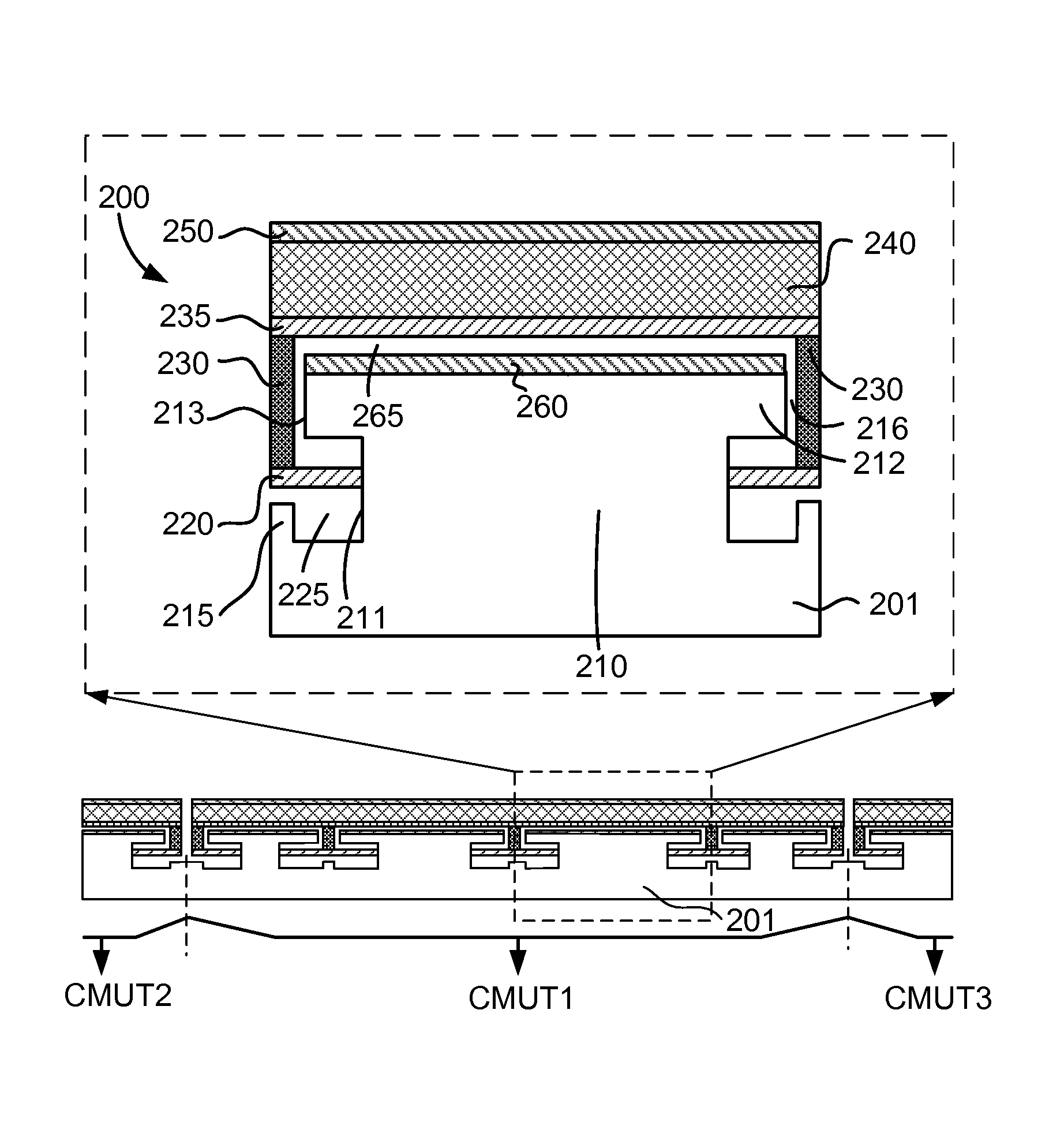
[0044]FIG. 2 shows an embedded-spring cMUT in accordance with the present invention. An enlarged view of a selected portion 200 of an embedded spring micro-electro-mechanical transducer (ESMUT) is placed within a rectangle of dashed lines. The ESMUT portion 200 is a part of a complete ESMUT element CMUT1 which may be a separate device alone or a part of a complete cMUT device having multiple cMUT elements (CMUT1, CMUT2 and CMUT3 as shown).

[0045]An ESCMUT unit is shown in the selected portion 200 in order to give structural context. The structure of the selected ESMUT portion 200 provides a basis to understand the complete ESMUT element as described in the several PCT patent applications referenced herein.

[0046]For certain application such as an ESMUT with a high operation frequency, a full ESMUT element or device may use only one basic unit of the ESMUT portion 200. For other applications, it may be preferred to use a combination of multiple basic units shown in FIG. 2, or any mixed...

second embodiment

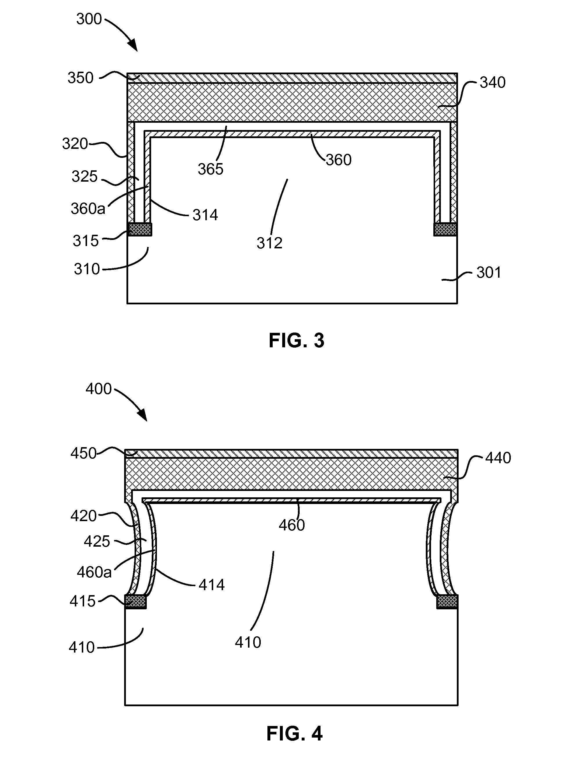
[0075]FIG. 3 shows an embedded-spring cMUT in accordance with the present invention. FIG. 3 is an enlarged view of a selected portion 300 of an embedded spring micro-electro-mechanical transducer (ESMUT). The ESMUT portion 300 is a part of a complete ESMUT element (not shown). Two springs are shown in order to give structural context.

[0076]The ESMUT portion 300 is built on a substrate 301, on which is a base including a lower base portion 310 and an upper base portion 312. A top plate 340 is disposed above the upper base portion 312 forming a gap 365 therebetween. A spring-like structure having a vertical bendable connector 320 connecting the top plate 340 and the lower portion 310 of the base through a spring anchor 315. The optional spring anchor 315 is added to insulate the vertical bendable connector 320 from the substrate 301 if needed.

[0077]In operation, bending of the vertical bendable connector 320 causes a vertical displacement of the top plate 340. As the top plate 340 is ...

third embodiment

[0080]FIG. 4 shows an embedded-spring cMUT in accordance with the present invention. FIG. 4 is an enlarged view of a selected portion 400 of an embedded spring micro-electro-mechanical transducer (ESMUT). The ESMUT portion 400 is a part of a complete ESMUT element (not shown). Two springs are shown in order to give structural context.

[0081]The ESMUT portion 400 is similar to the ESMUT portion 300 shown in FIG. 3. However, the ESMUT portion 400 is characterized by a spring-like structure having a curved bendable connector 420 connecting the top plate 440 and the lower portion 410 of the base. Compared to the straight vertical bendable connector 320, the curved bendable connector 420 may be easier to bend and have more controllable and more consistent bending behavior. A spring anchor 415 similar to the spring anchor 315 in FIG. 3 is also used for further insulation.

[0082]In a cMUT configuration, the top plate 440 further has a top electrode 450 as one of its transducer members. Corre...


PUM


Abstract

A micro-electro-mechanical transducer (such as a cMUT) is disclosed. The transducer has a base having a lower portion and an upper portion; a top plate disposed above the upper portion of the base forming a gap therebetween; and a spring-like structure disposed between the top plate and the lower portion of the base. The spring-like structure has a spring layer connected to the lower portion of the base and a spring-plate connector connecting the spring layer and a top plate. In an alternate embodiment, the spring-like has a vertical bendable connector connecting the top plate and the lower portion of the base. The spring-like structure transports the top plate vertically in a piston like manner to perform the function of the transducer. Fabrication methods to make the same are also disclosed.

Description

PRIORITY[0001]This application claims priority from U.S. Provisional Application Ser. No. 60 / 705,606, filed Aug. 3, 2005, and Ser. No. 60 / 744,242, filed Apr. 4, 2006, which applications are incorporated herein by reference in their entirety.[0002]This application further incorporates herein by reference in entirety the following:[0003]International Application (PCT) No. PCT / IB2006 / 051567, entitled METHODS FOR FABRICATING MICRO-ELECTRO-MECHANICAL DEVICES, filed on May 18, 2006;[0004]International Application (PCT) No. PCT / IB2006 / 051568, entitled MICRO-ELECTRO-MECHANICAL TRANSDUCERS, filed on May 18, 2006;[0005]International Application (PCT) No. PCT / IB2006 / 051569, entitled MICRO-ELECTRO-MECHANICAL TRANSDUCERS, filed on May 18, 2006; and[0006]International Application (PCT) No. PCT / IB2006 / 051948, entitled MICRO-ELECTRO-MECHANICAL TRANSDUCER HAVING AN INSULATION EXTENSION, filed on Jun. 16, 2006.FIELD OF THE INVENTION[0007]The present invention relates to micro-electro-mechanical devic...

Claims


Application Information

Patent Timeline
Patent Type & Authority Patents(United States)
IPC IPC(8): H01L41/00
CPCB06B1/0292B81C1/00103G01N29/2406H03H3/0072H03H9/02259H03H9/2405H03H9/462H01L2924/0002H01L2924/00
Inventor HUANG, YONGLI
Owner KOLO MEDICAL (SUZHOU) CO LTD
Learn More