Apparatus for capturing on object scene

Inactive Publication Date: 2009-07-21
BODENSEEWERK GERATETECHNIK GMBH
View PDF21 Cites 12 Cited by
  • Summary
  • Abstract
  • Description
  • Claims
  • Application Information

AI Technical Summary

Benefits of technology

[0014]The use of a cardan system comprising the pitch frame and the roll frame makes it possible to capture a large spatial angle. In a suitable structural configuration the object-side system portion can be pivoted with respect to the roll frame about the pitch axis through more than 90°, without that movement being impeded by the roll frame. The rotation of the roll frame about the roll axis permits orientation of the system portion within an angle of 360°. In contrast to known roll-pitch systems however the detector is not arranged on the pitch frame but is arranged fixedly with respect to the structure on the roll axis. That is made possible by virtue of deflection of the imaging beam path. The imaging beam path is firstly deflected by the first beam deflection means in such a way that it extends along the pitch axis. The beam path is then not influenced by pivotal movement of the object-side system portion about the pitch axis, except for image rotation. The second beam deflection means which are rotatable with the roll frame capture the beam path deflected in that way, on the pitch axis, and deflect it in such a way that it extends along the roll axis. The detector which is fixed with respect to the structure is disposed on the roll axis which in fact is fixed with respect to the structure.

Problems solved by technology

That makes it difficult to take out the signals of the detector.

Method used


Image

  • Apparatus for capturing on object scene
  • Apparatus for capturing on object scene
  • Apparatus for capturing on object scene

Examples


Embodiment Construction

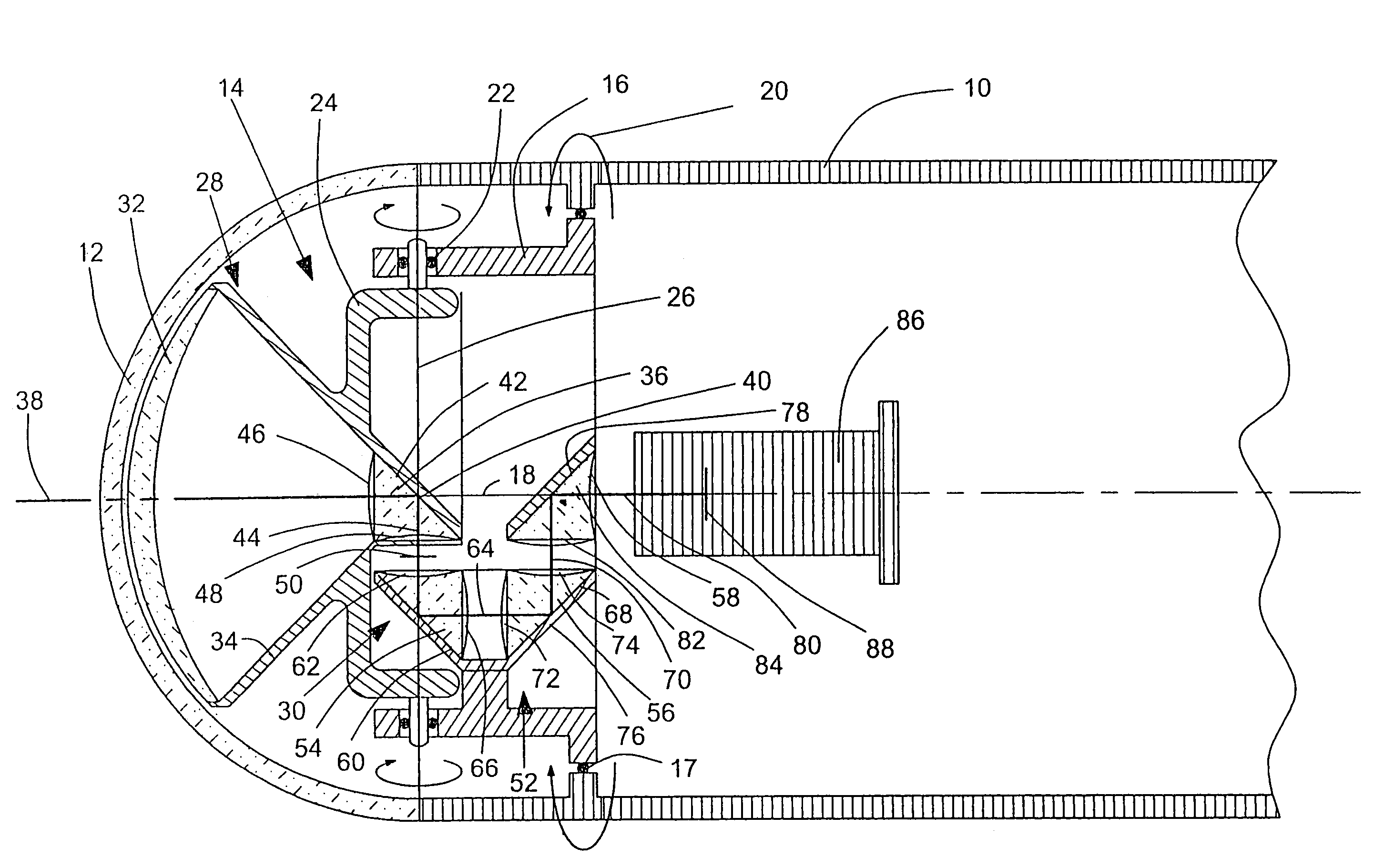
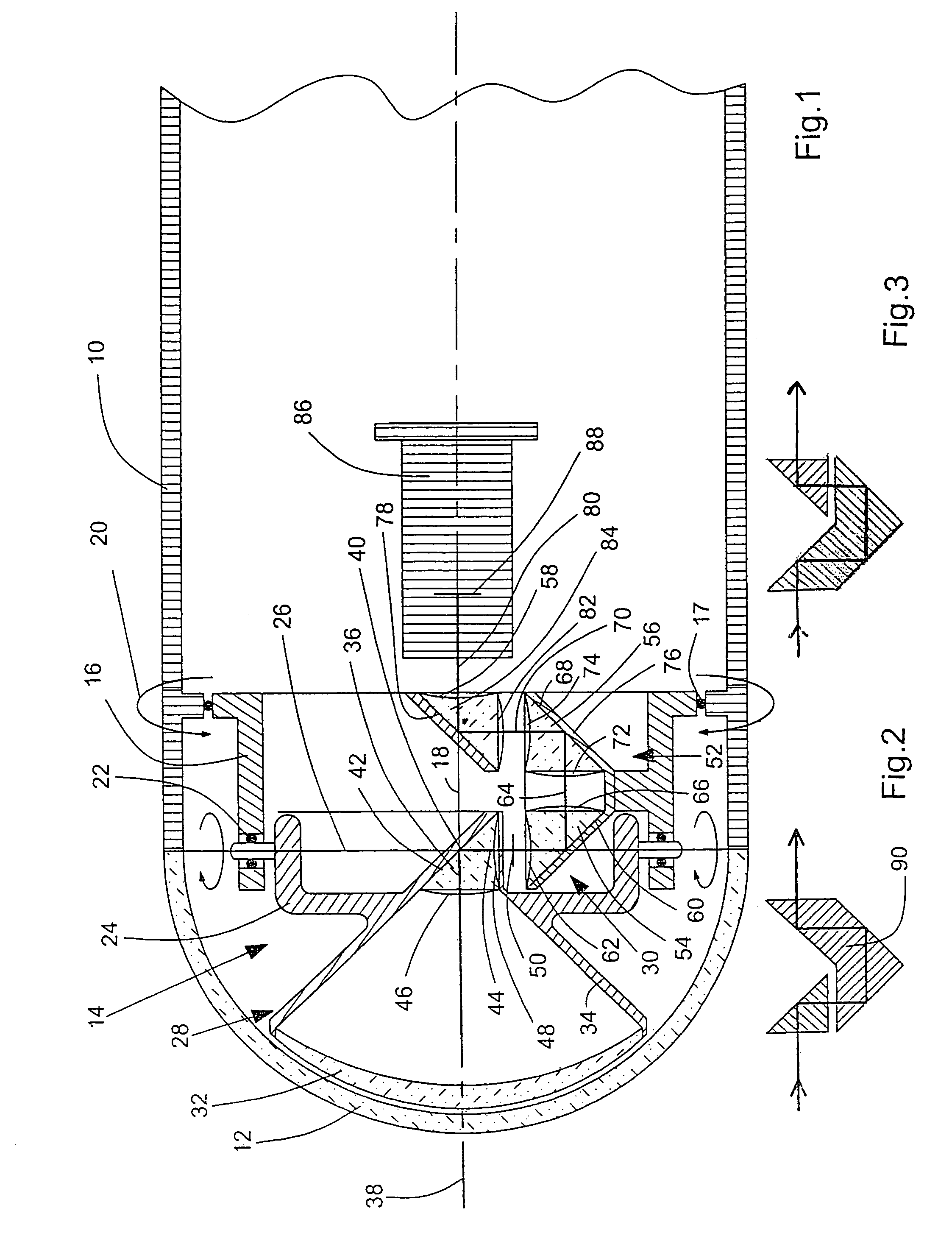
[0021]In FIG. 1 reference 10 denotes the structure of a target-tracking missile. The nose of the missile is formed by a hemispherical dome or window 12. A seeking head 14 is disposed behind the dome 12.

[0022]The seeking head 14 has a roll frame 16. The roll frame 16 is supported in bearing means 17 rotatably about a roll axis 18. This is indicated in FIG. 1 by the arrows 20. The roll axis 18 here coincides with the longitudinal axis of the missile. A pitch frame 24 is supported in the roll frame 16 pivotably about the pitch axis 26 by way of bearing means 22. The roll frame 16 permits a pivotal movement of the pitch frame and the parts carried therein about the pitch axis 26 through an angle of about 180°, that is to say 90° rearwardly in FIG. 1 and 90° forwardly.

[0023]Carried in the pitch frame 24 is an object-side system portion 28 of an imaging optical system which is generally identified by reference 30. The object-side system portion 28 includes a lens 32 which is mounted in a ...


PUM


Abstract

An apparatus for capturing an object scene, in particular a seeking head for target-tracking missiles, such that, with a detector 86 in fixed relationship with a structure, it is possible to capture a large spatial angle. For that purpose the imaging optical system (30) has a system portion (28) facing the object scene which is pivotable with a pitch frame (24) about a pitch axis (26) perpendicular to a roll axis (18). The pitch frame (24) is mounted pivotably about the pitch axis (26) in a roll frame (16) which is supported in the structure (10) rotatably about the roll axis (18). The system portion (28) includes first beam deflection structure (36) by which the imaging beam path of the imaging optical system (30) is deflectable in a direction along the pitch axis (26). The imaging optical system (30) further includes second beam deflection structure (52) which are rotatable with the roll frame (16) and by which the deflected beam path is picked up along the pitch axis (26) and deflected in the direction of the roll axis (18). The detector (86) is arranged on the roll axis (18).

Description

BACKGROUND OF THE INVENTION[0001]1. Field of the Invention[0002]The invention concerns an apparatus for capturing an object scene, including an imaging optical system which is pivotable relative to a structure and a detector which is fixed with respect to the structure and on which an image of the object scene is produced by the imaging optical system.[0003]This apparatus may involve a seeking head for a target-tracking missile. The invention however can also be used in relation to an “all-around search arrangement”, that is to say a stationary apparatus by which a large field of view is continuously scanned. Such an all-around search arrangement is described and illustrated for example in EP 0 629 890 B1.[0004]2. Discussion of the Prior Art[0005]In known seeking heads for target-tracking missiles with a detector which is fixed with respect to the structure, an imaging optical system is supported cardanically about two axes which extend substantially perpendicularly to the longitudi...

Claims


Application Information

Patent Timeline
IPC IPC(8): H04N7/18G02B23/12G02B26/08H04N5/225
CPCG02B23/12H04N5/2259G02B26/08H04N23/58
Inventor BAUMANN, RAINERECKHARDT, REINER
Owner BODENSEEWERK GERATETECHNIK GMBH
Why Eureka
Try Eureka